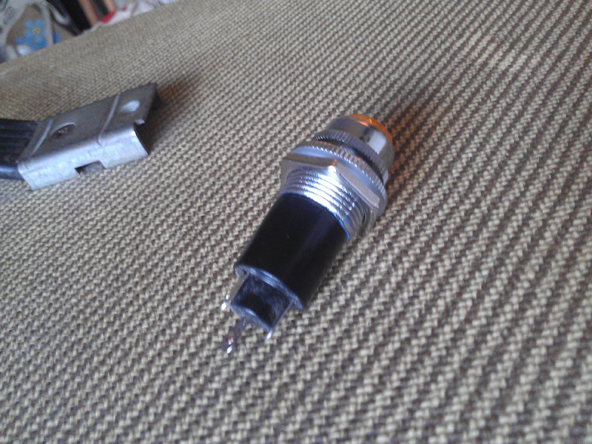
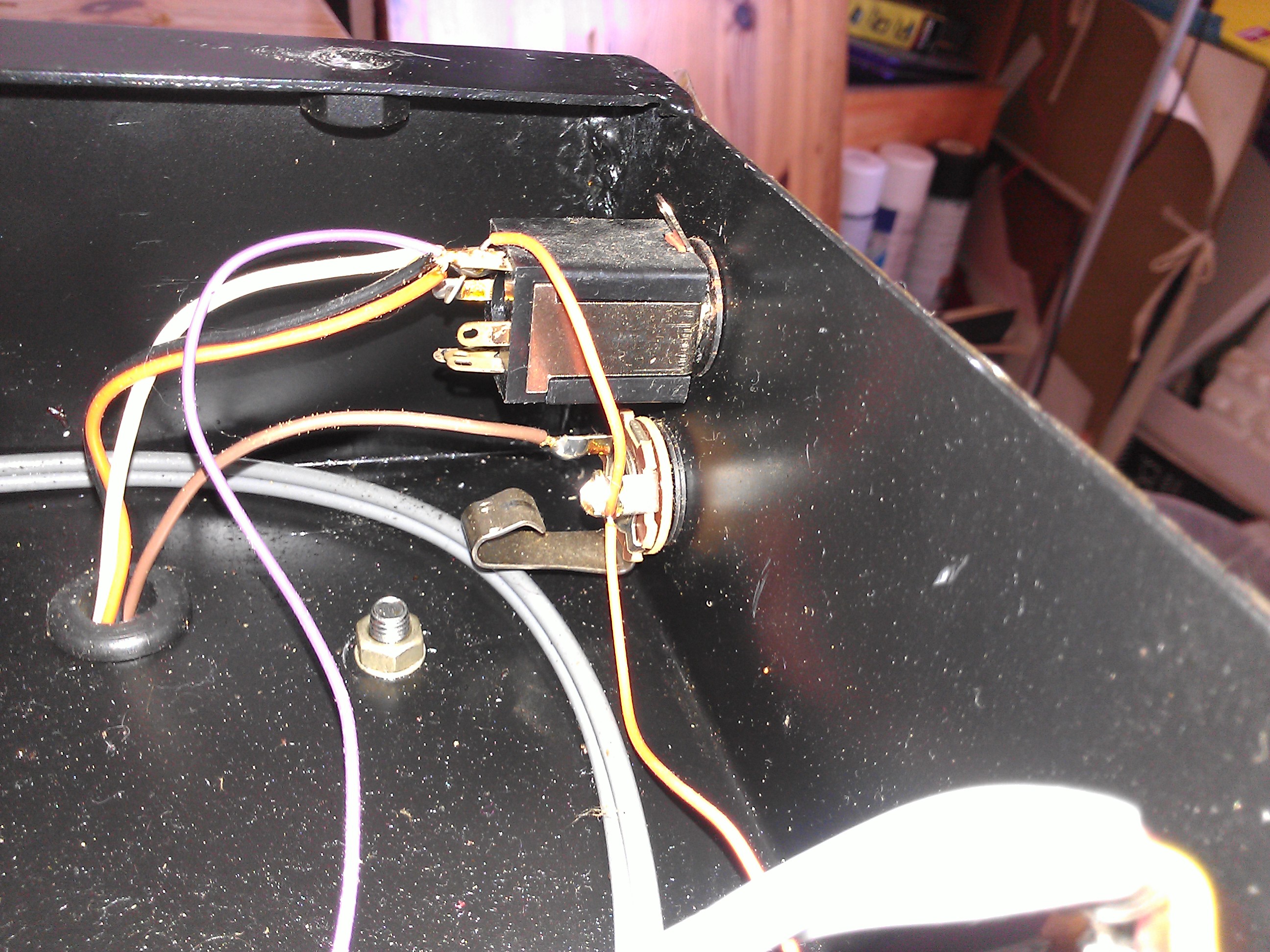
So I want to replace the loose, shitty bulb on my new amp with a nice orange Fender bulb. But the one I have to replace it has three tags instead of two, like the current bulb. So what's the craic? Should I just ignore one of them? If so, which?
Here they are:
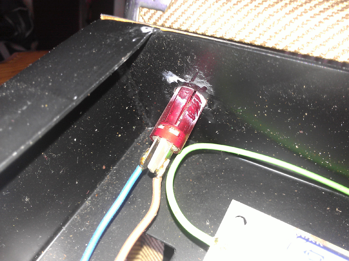
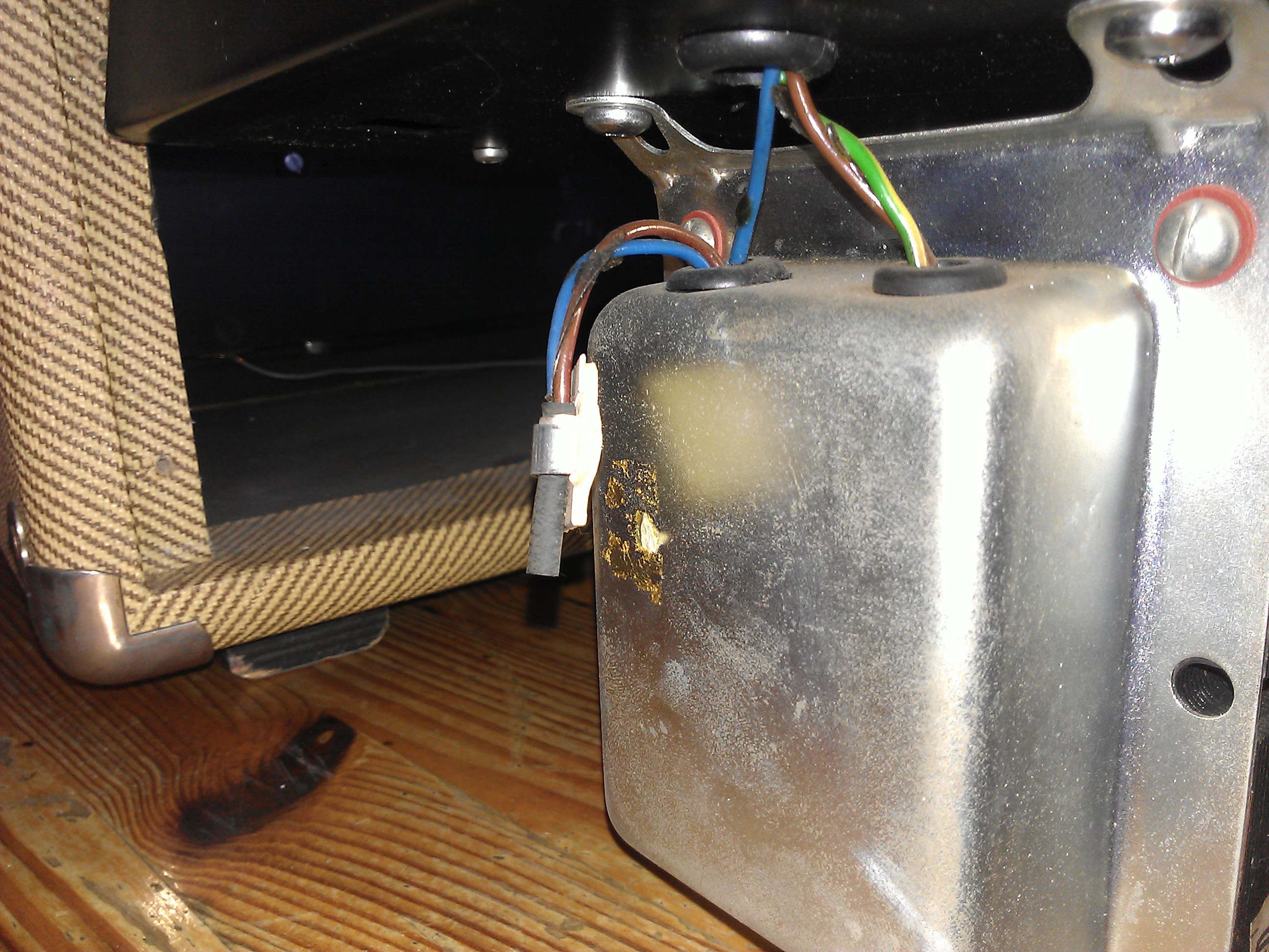
Note the superglue around the current bulb to keep it from freewheelin' in the socket, because it's a bit shit.
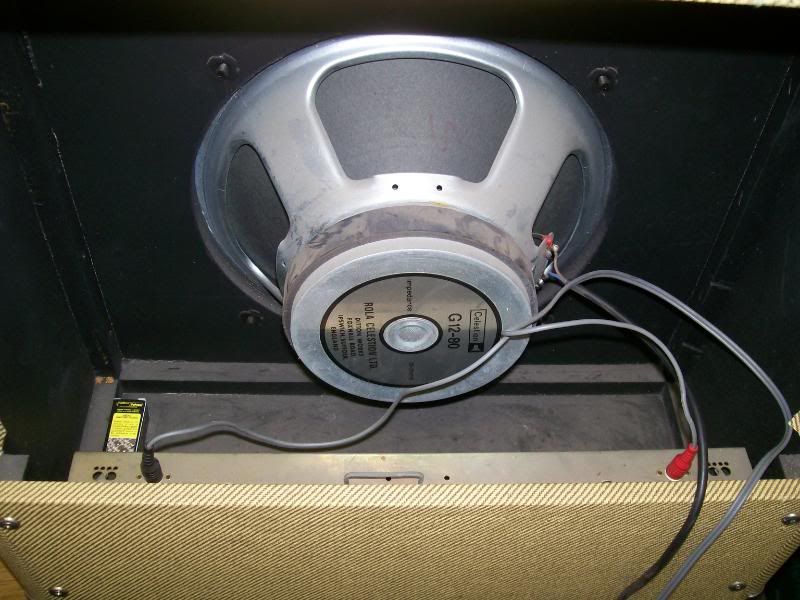
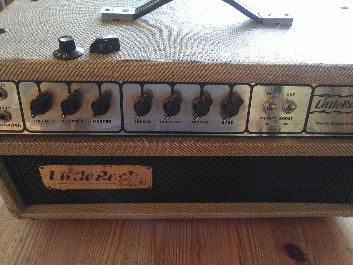
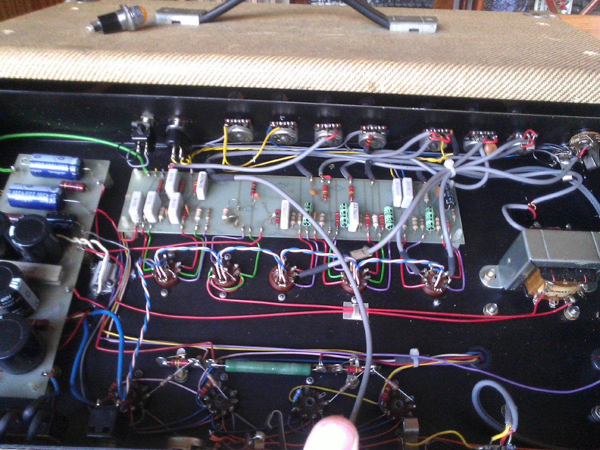
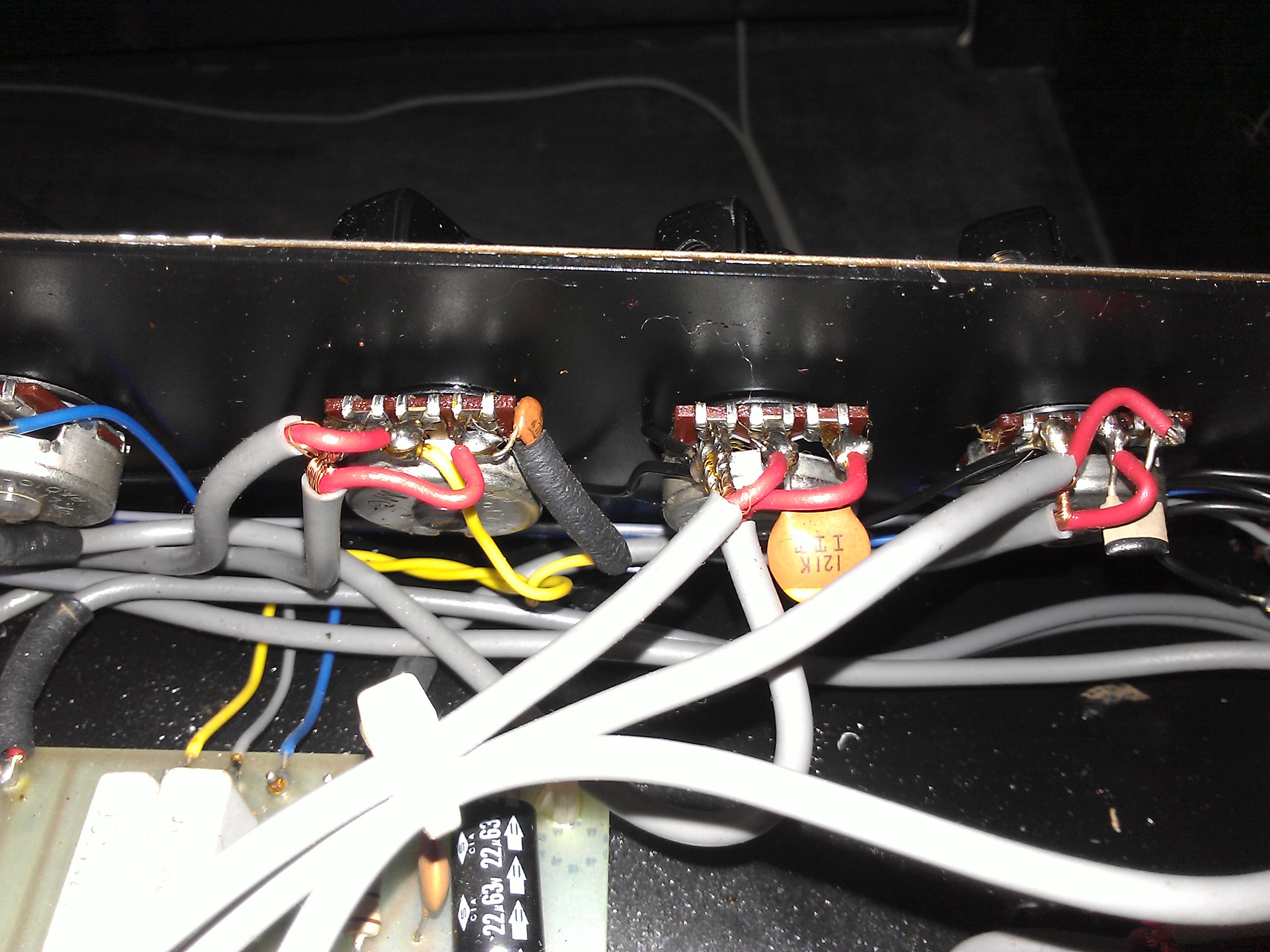
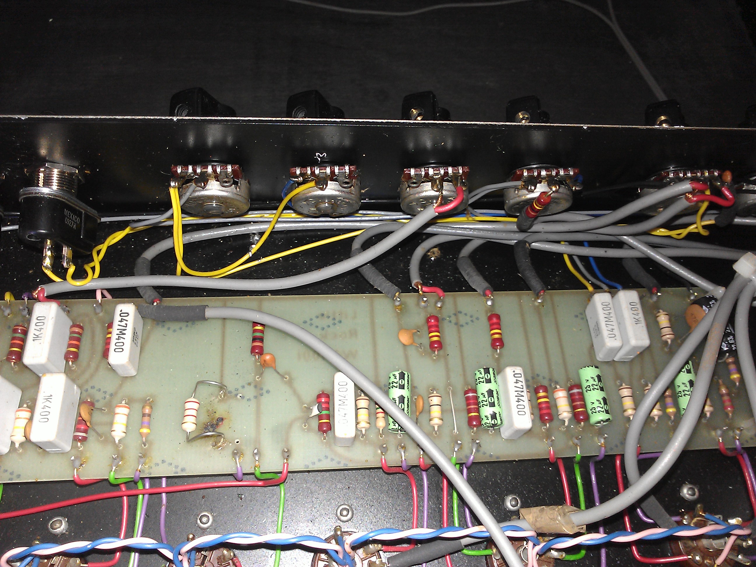
Also, for those interested in this sort of thing, I replaced the knobs and took a picture of the guts. Enjoy.
No schematic as far as I could see, I could hardly find the bare minimum of info on this amp. I'll have to test the pilot lights with a multimeter tomorrow.
So if one of the lugs is earth and the existing pilot light doesn't appear to have one, does that mean I can just leave it alone? Or will it need to be soldered to something? Like, to the case or something? Also, is it likely that the earth is the middle lug?
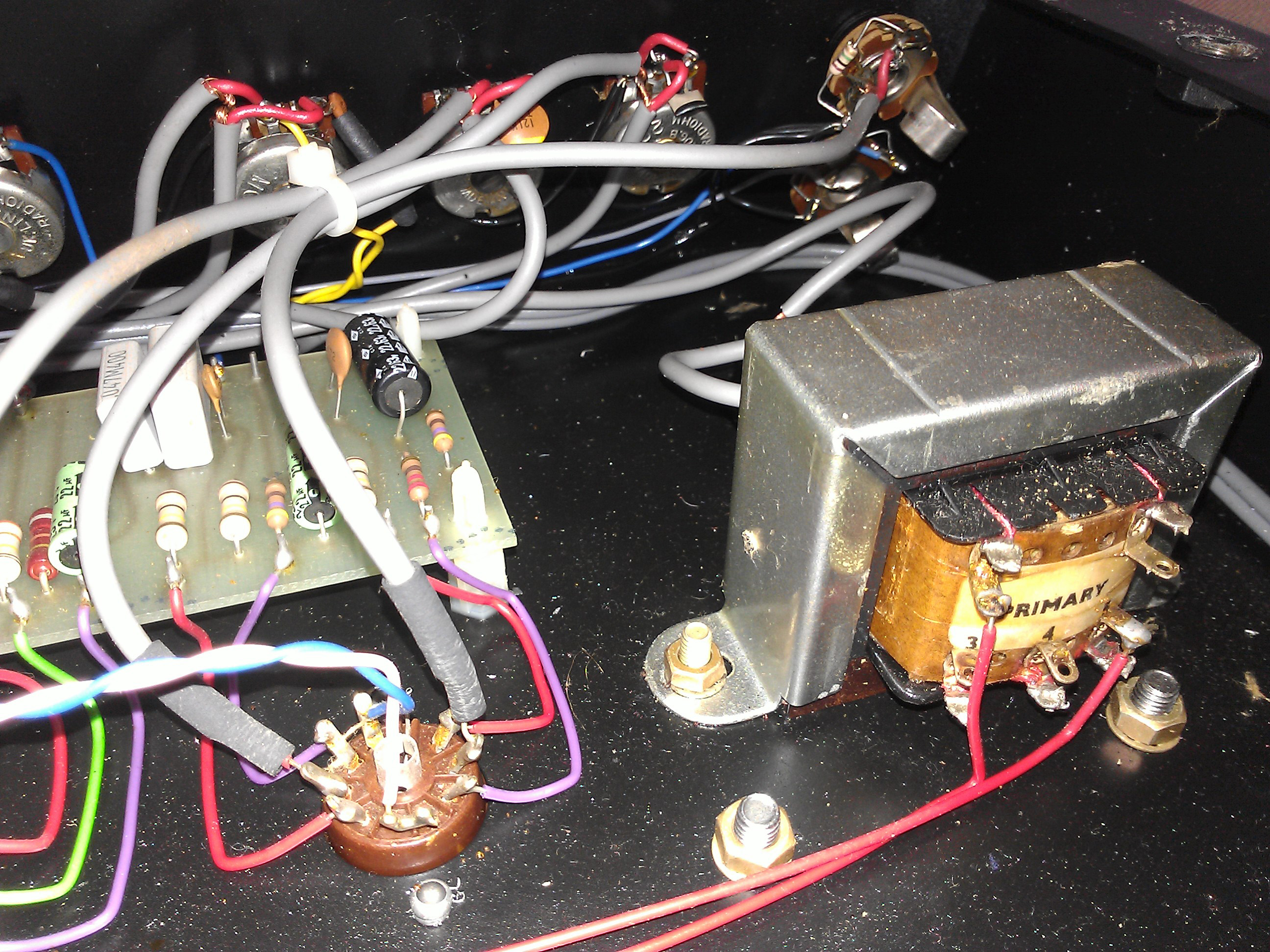
Can you take more pics inside the chassis, including the output transformer and speaker sockets so we can work out what's going on with the speaker impedance?
I am guessing that the old one is earthed through the casing. And that the new one the earth lug will connect to the outside metal of the bulb so you probably wouldn't need to earth it. However that is a guess that you should wait for someone more electric savvy to confirm.
The old one looks like a standard plastic-case mains neon of that era, two tags separated by a plastic divider, no earth. I have a couple floating around.
What exactly is the new lamp? Does it use a 240V bulb? If it's Fender-like, isn't it a 6v bulb? I expect that both side tags are the same electrode and the end one is the other, the metalwork of the bezel being earthed through the case. Probably shouldn't use it with the 240V I'd expect to find on the neon.
timhulio wrote:The neon pilot light on my MM Bass amp is 120v, also used on Sunn amps.
Yes, it could be run off the 110/120V tap if the mains transformer has a 110/120V tap, but this was built in Sunderland IIRC and the power leads going to the lamp appear to be blue and brown like UK mains. Schematics for the White amps are rarer than Penny Blacks.
The voltage is probably embossed in the plastic of the neon, if it's anything like my old ones. Or give us enough pics that we can work out the schematic
Okay, I had a reaaaallly close look at the current bulb and it said 240V AC on it. However, the orange replacement I have says it's 6,3V 15 amps.. I take it it isn't going to go? So I need a 240V replacement and it'll just drop in, right? Or would I be able to just buy a 240V bulb to fit into the enclosure? I should probs have figured this out first... ah well.
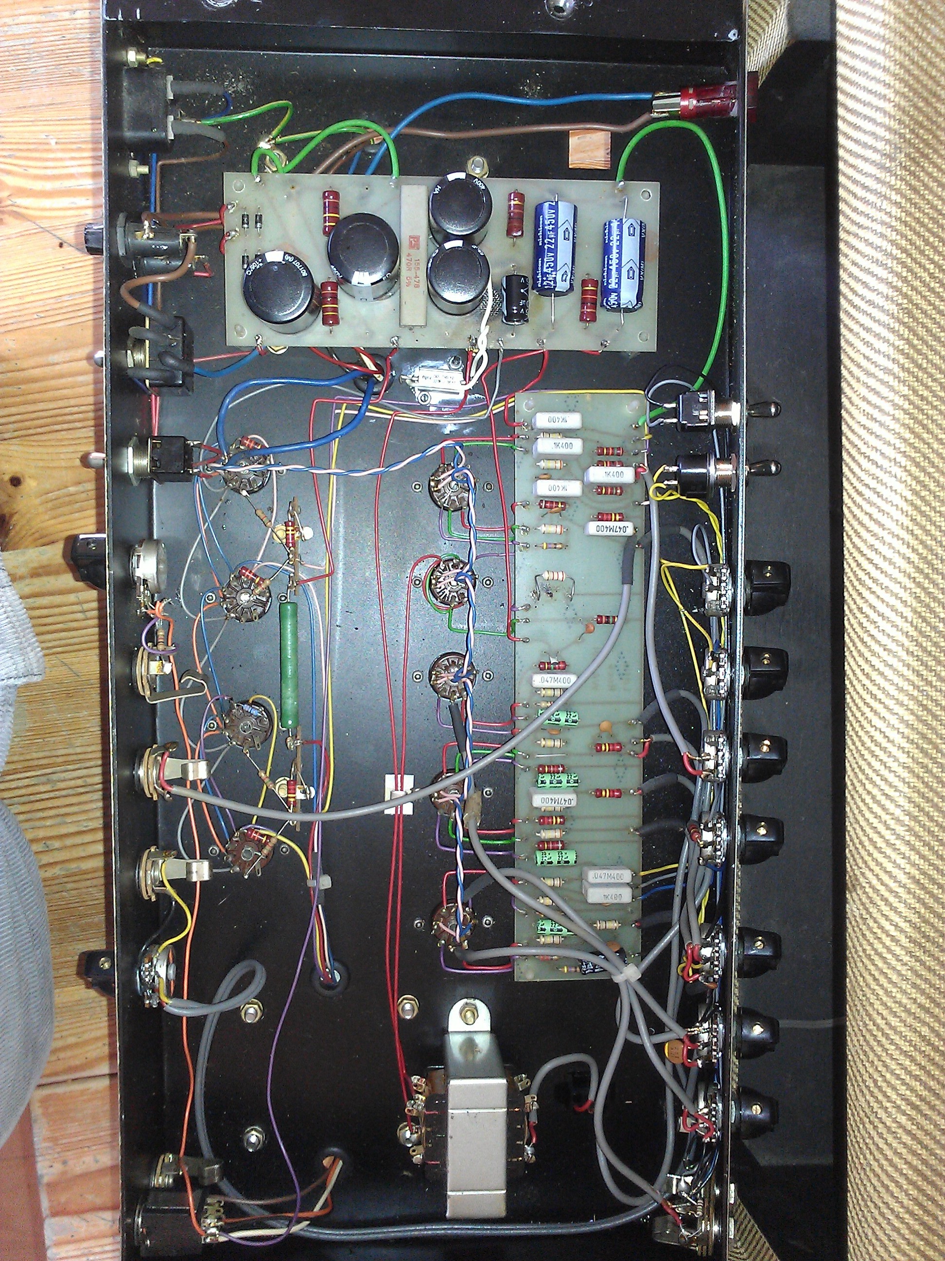
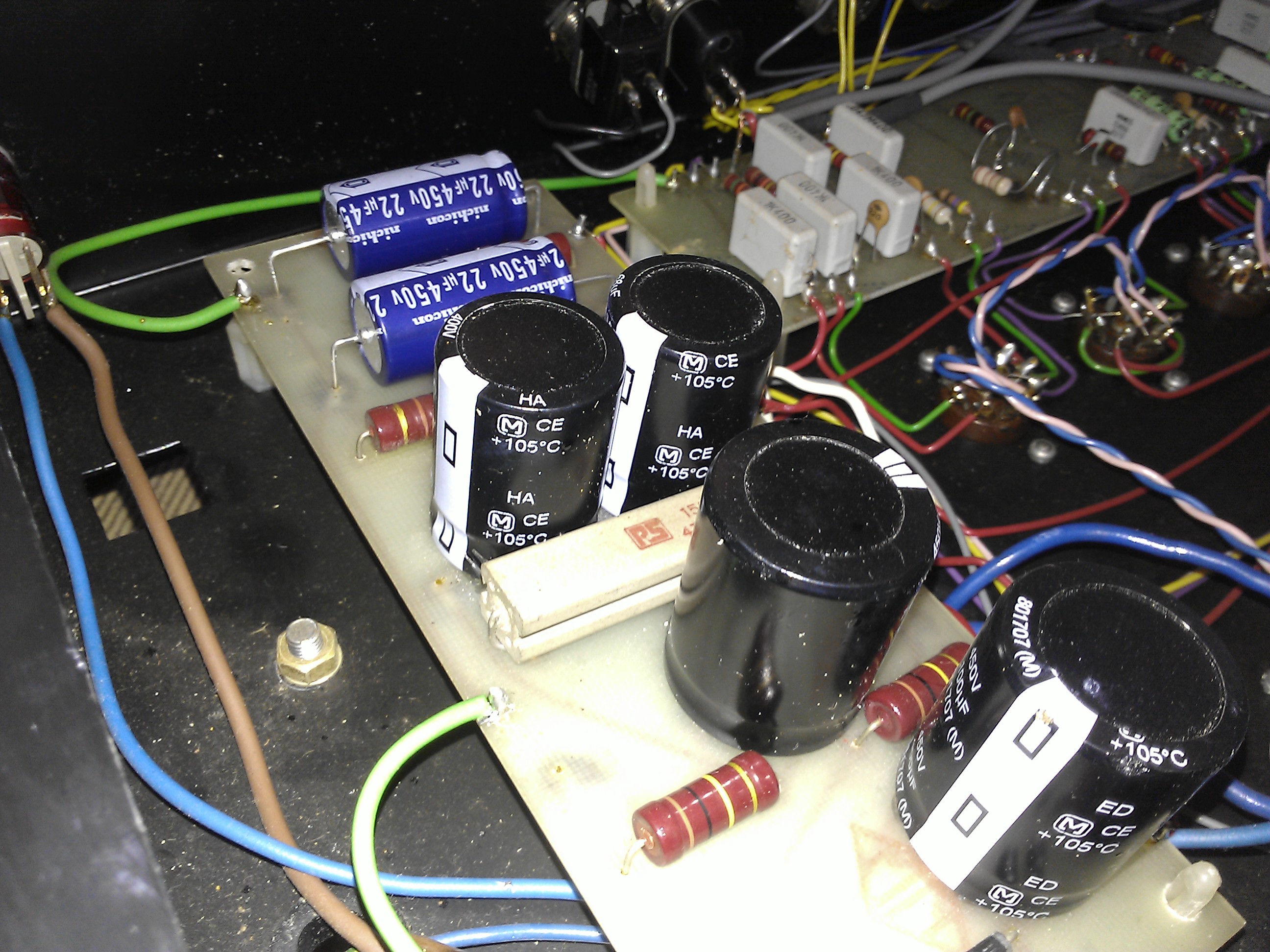
Anyway, here are the extra pics people wanted of the guts of the amp. If anyone can help figure out the Ohms and shit from this I'd be very grateful.
I'm guessing you want to change the look (as you've changed the knobs) so I won't point out Maplin's square panel neon (red, green or amber) with a locking nut, at 99p.
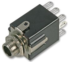
I still can't make out from the photos what's happening with those wires and the switched jack, but I've seen something very similar, very recently and I'm racking my brains to remember where. I suspect the unswitched (bottom) jack is for a 16 ohm speaker and the switched (top) jack for an extension cab with a second 16 ohm speaker. I think the switched jack socket is an MJ-188 like this: but from the current pics I can't make out the connections.
Data sheet here.
Well, I registered with the Vintage Amps BB where mrcustard and welshman have posted before, to ask for info. From pics, it looks like mrcustard was the previous owner of this (and other White amps), and welshman owns the combo version (pic of the speaker above). Unfortunately, noobs posts have to be approved and it doesn't look as if they're in any hurry to do this.
Only answer so far is from someone who has got the wrong end of the stick and suggested I measure the DC resistance of the speaker.
For the moment, I would assume the lower-when-assembled (unswitched) socket is for a 16 ohm internal speaker, and the switched one for an extension 16 ohm that will put them in parallel and select an 8 ohm tap. If you can give me more photos around the switch so I can see exactly which wires connect to which tags (or if you can draw it out) we may be able to confirm.
If you have a meter you could plug a bare jack plug into each socket and check whether you get zero ohms (or the same as when you connect the probes together) between the tips on each, and between the rings on each. You should get a small resistance between tip and ring, and if you unplug the "extension" jack that small resistance should increase; but these are quite small and not all meters may be able to tell the difference.
As it's a 4x EL84 setup you'll probably get a maximum of around 40W out of it.
From what I could gather the guy I bought it off on eBay had bought it off the guy on the Vintage Amps forum a few months ago and basically copied exactly the same auction description for his, so it has already passed through somebody elses hands between the two of us; I assume the previous owner had some questions he couldn't figure out, too.
I think I read somewhere that it was originally intended to output 50 watts with KT88s or something. Dunno if that's the Matamp/White amplification crossover causing any confusion or not, I know very little about this sort of thing.
I'll try and take more pictures tonight, I spent all of last night re-attaching the Vox logo to the AC30 as we're intending on selling it now considering we now have three valve amps in the house.
To be clear, do you need good pictures of the wiring between the speaker output sockets and the switches? I might be able to draw it out as well.
I'm probably going to be buying the speaker cabinet this weekend, probably from Zilla cabs, and going with an Eminence Swamp Thang and Wizard speaker setup. If I buy both in 16ohm versions, how do I wire them? In series or parallel?


 but from the current pics I can't make out the connections.