


Whisker Biscuit schematic help?
Moderated By: mods
Whisker Biscuit schematic help?
Thinking of making a Whisker Biscuit with two Bazz Fusses in series rather than one. However, I am still learning how to read circuits, so I was wondering if someone could help me isolate the Bazz Fuss from the Whisker Biscuit schematic? I think I could figure out the rest afterward.
Doog wrote:Tone is stored in the balls
theshadowofseattle wrote:That's why there's two: one for pee, one for tone.

 (she/they)
From the second 100n cap to right before it goes into the tone stack, which is the split 33k resistor and the 4n7 cap. The full isolated circuit would have another 100n cap right there to prevent DC leakage.
If you wanted to do two in series, take it all from the second 100n cap up to where it splits to the tone stack, and repeat it.
If you wanted to do two in series, take it all from the second 100n cap up to where it splits to the tone stack, and repeat it.
euan wrote: I'm running in monoscope right now. I can't read multiple dimensions of meta right now
Now, if I wanted to put a sustain pot, I would put it just before the second 100nF capacitor, correct? I feel like that's wrong, if so, explain where and how I would put in a sustain pot? Here's what the new schematic looks like:

Doog wrote:Tone is stored in the balls
theshadowofseattle wrote:That's why there's two: one for pee, one for tone.
(she/they)If I recall right, the "sustain" pot was really a gain pot and in the BMP was just before the major gain stage. In other words, would be before the first Bazz Fuss stage. If I were you, that's where I'd put it here. It limits the amount going into the gain stages and thus making it not as raunchy sounding. Smaller signal == less clipping.
It ought to be a pot going into the top leg of it, with the wiper being the "output" going into the gain stage. Possibly a small resistor on bottom leg going to ground to provide a minimum gain.
It ought to be a pot going into the top leg of it, with the wiper being the "output" going into the gain stage. Possibly a small resistor on bottom leg going to ground to provide a minimum gain.
euan wrote: I'm running in monoscope right now. I can't read multiple dimensions of meta right now
Great, that's what I was also thinking, especially after finding this this detailed explaination of the Big Muff circuit. At the bottom, there is a schematic for the Big Muff. In the Big Muff schematic, I see that going out of the first gain stage, there is a 1uF cap just before a 100k pot leading into the second gain stage and a 1k resistor bettwen the pot and ground, which I believe is what you mentioned with the resistor for minimum gain. So logically, all I need is to put that in the same place, correct?
Here's the new schematic in which I added a gain pot. I think this should work.

Here's the new schematic in which I added a gain pot. I think this should work.
Doog wrote:Tone is stored in the balls
theshadowofseattle wrote:That's why there's two: one for pee, one for tone.
(she/they)

-
JohnnyTheBoy

- .

- Posts: 542
- Joined: Fri Feb 04, 2011 2:39 pm
- Location: Middle England
- Contact:
I fully intend to, but first, I will breadboard board the current circuit I have. Then, if it sounds okay, I plan to try out a few mods, one at a time, then all of them at a time if they work. I plan on making this thing some crazy ass customizable monster.

- ~A switch to turn each Bazz Fuss on seperately (BF 1/BF 1&2/BF 2)
~Two switches to change the diode in each Bazz Fuss (switch one - Si/none/Ge, switch two Si/LED/Ge)
~Tone bypass switch
~Switch to select between regular tone stack or flat mids tone stack
~Clean blend
Doog wrote:Tone is stored in the balls
theshadowofseattle wrote:That's why there's two: one for pee, one for tone.
(she/they)To clarify a bit more, you take the signal from the 1u cap into the "top" leg of the pot, attach the wiper to the 100n cap, a smallish resistor (1k is fine) to the bottom leg, then go to ground.Pens wrote:YepNickS wrote:Wiper to the 100n cap, small resistor (1K) to the bottom of the pot is what he meant.
This creates a voltage divider, which will effectively cut the signal down into a smaller wave form when turned down.
euan wrote: I'm running in monoscope right now. I can't read multiple dimensions of meta right now
Oh, one tweak I would suggest to your schem is a large resistor to ground just in front of the first cap. I'm not sure what the purpose of that 33k in series with the signal is aside from input impedance, but it's generally a good idea to have a resistor in front of that cap to provide a path to ground for the other leg of that input cap. This helps avoid the "pop" you hear with some pedals when they are engaged, basically the cap charges on the other side of it but has no place to dump to until the pedal is engaged, which then dumps the charge into the signal path and makes the pop. I'd probably change the 33k up front there into a 100k to ground instead.
euan wrote: I'm running in monoscope right now. I can't read multiple dimensions of meta right now
Yep, that's one reason why. Particularly with old low-gain germanium transistors, where the input impedance of the transistor is effectively gain x emitter resistor (100R). With higher-gain transistors it gets a whole lot more complicatedPens wrote:Oh, one tweak I would suggest to your schem is a large resistor to ground just in front of the first cap. I'm not sure what the purpose of that 33k in series with the signal is aside from input impedance,
► Show Spoiler
I've drawn out a couple of the mods that I've mentioned:
Alternatively, I'm considering extending the tone bypass to include the last stage, which is essentially just an amp to bring counter act the volume cut that comes with the tone stack. Therefore, if I want to make the tone bypass footswitchable, I don't have to worry about the massive volume boost that happens. I guess I will just have to try it out myself, so I will post here when I do.

- ~two separate switches to bypass each gain stage
~one switch to bypass the tone stack
Alternatively, I'm considering extending the tone bypass to include the last stage, which is essentially just an amp to bring counter act the volume cut that comes with the tone stack. Therefore, if I want to make the tone bypass footswitchable, I don't have to worry about the massive volume boost that happens. I guess I will just have to try it out myself, so I will post here when I do.
Doog wrote:Tone is stored in the balls
theshadowofseattle wrote:That's why there's two: one for pee, one for tone.
(she/they)That's going to be interesting, as at full "Gain" the collector load on Q1 will be a little under 1K instead of the intended 10K. This reduces the open-loop gain by a factor of 10. You may find that the Gain control appears to do very little over a wide range, and that most of the stage gain has disappeared.daftsupernova wrote:I fully intend to, but first, I will breadboard board the current circuit I have.
Yeah as drawn I don't see that gain control doing much. It needs to be a voltage divider there.NickS wrote:That's going to be interesting, as at full "Gain" the collector load on Q1 will be a little under 1K instead of the intended 10K. This reduces the open-loop gain by a factor of 10. You may find that the Gain control appears to do very little over a wide range, and that most of the stage gain has disappeared.daftsupernova wrote:I fully intend to, but first, I will breadboard board the current circuit I have.
euan wrote: I'm running in monoscope right now. I can't read multiple dimensions of meta right now
No, the configuration of the gain pot is only going to change the amount of resistance going into the gain stage, which isn't going to do what you want it to do.
You need a voltage divider. Look at the below, at the Sustain knob, for how to configure this. You will keep that resistor there between the pot and ground, but this his how it ought to be set up.
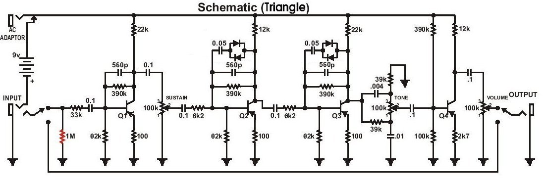
You need a voltage divider. Look at the below, at the Sustain knob, for how to configure this. You will keep that resistor there between the pot and ground, but this his how it ought to be set up.
euan wrote: I'm running in monoscope right now. I can't read multiple dimensions of meta right now