Gut Shots

Pickups, pedals, amps, cabs, combos

Moderated By: mods

User avatar
Mike
I like EL34s
Posts: 39170
Joined: Thu Apr 20, 2006 8:30 am
Location: Edinburgh, Scotland
Contact:

Gut Shots

Post by Mike »

I haven't rebiased the JVM since I pulled two tubes which isn't major but was a little naughty. Stock bias setting is 30mA per tube, I had set it to 70mA a side, so 35mA per tube when I biased it with four tubes present.. when I checked on it the sides were at 42mA and 38.8mA which is in the operating region (although 42mA is close to the max 45mA I would set EL34s at) so I rebiased and had a play at various settings to see what effect it had (not much, mainly in the fullness of the sound vs. cut of the attack) before settling on both tubes at 39mA each.

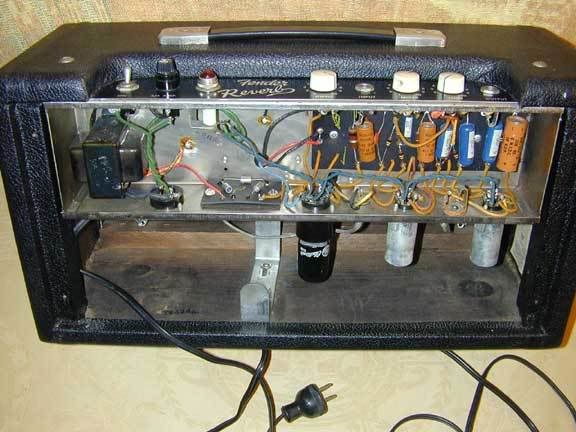
Anyway, I took some gut shots aswell, I like looking at them, so if you can be arsed, post some of yours.

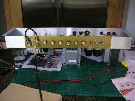
Here's a cool trick for biasing a head, flip the head and rest it on the top of the headcase so the tubes and transformers hang into the void yet the chassis is supported by the headcase edges and at a solid and good working position for you
Image

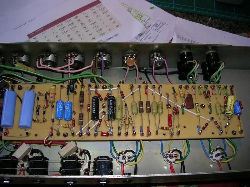
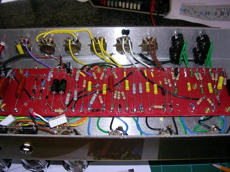
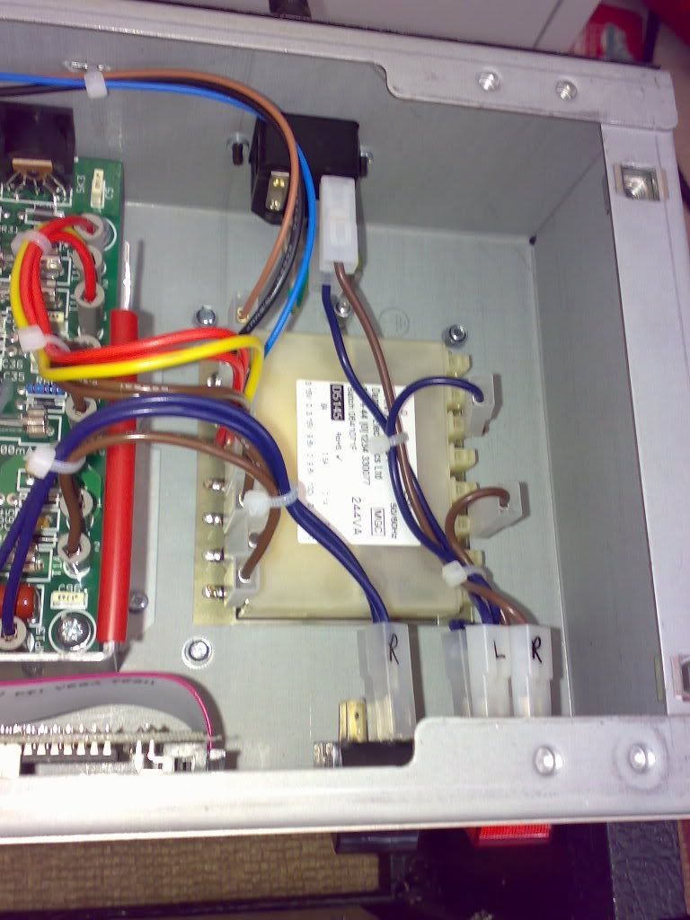
Starting from the input side (right as you look at it normally). this is the bottom of the Output Transformer, it's a JCM800 2203 spec Dagnall (i.e. good).
Also see the speaker output jacks and their attached board attached the 4, 8 and 16 ohm taps.
Image

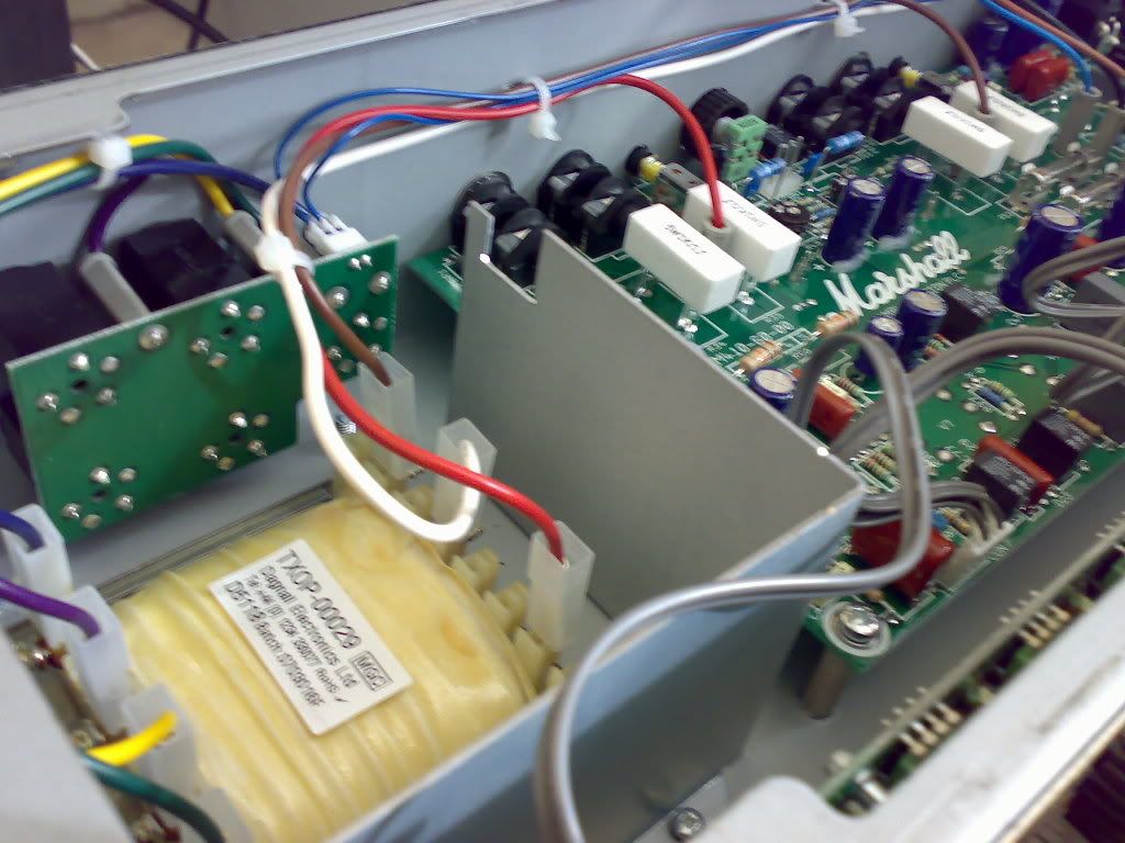
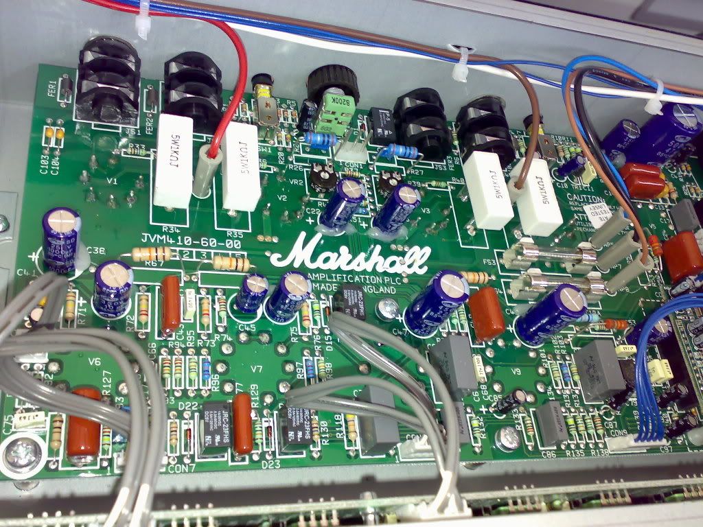
Main board and the preamp and power amp sections, you can see the large white resistors which are the screen grid resistors. They're large and white because they are high wattage resistors. Above the "Marshall" and the caps is the bias probe connector and the two pots for adjusting the bias. The sockets are the inputs/outputs for the serial and parallel effects loops
Image

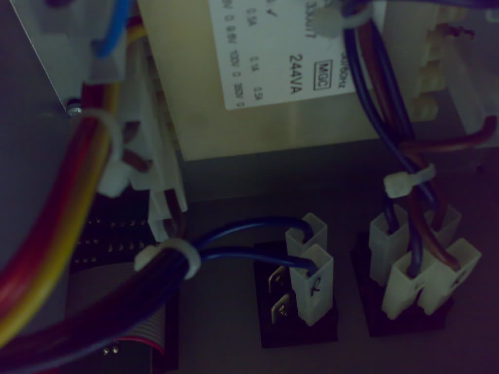
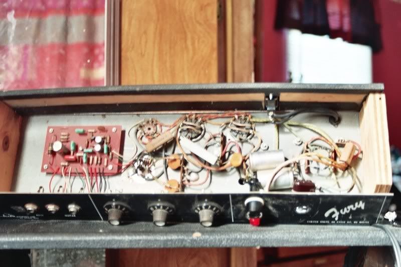
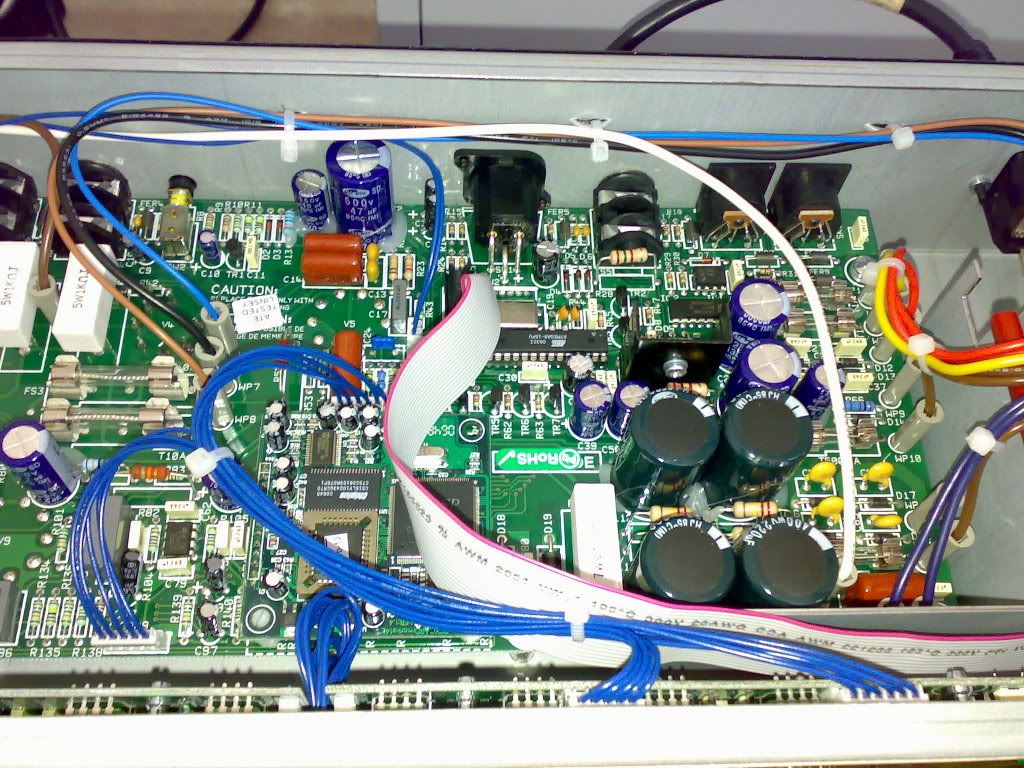
Further along the main board, you can see the two fuses, centre bottom is the DSP for the Plate Reverb. The ribbon and blue cables go to the vertical board you can see in the bottom of the image, which houses all the knobs for preamp EQ, gain etc and the Master controls. the brown, blue and black connectors are from the Power Transformer
Image

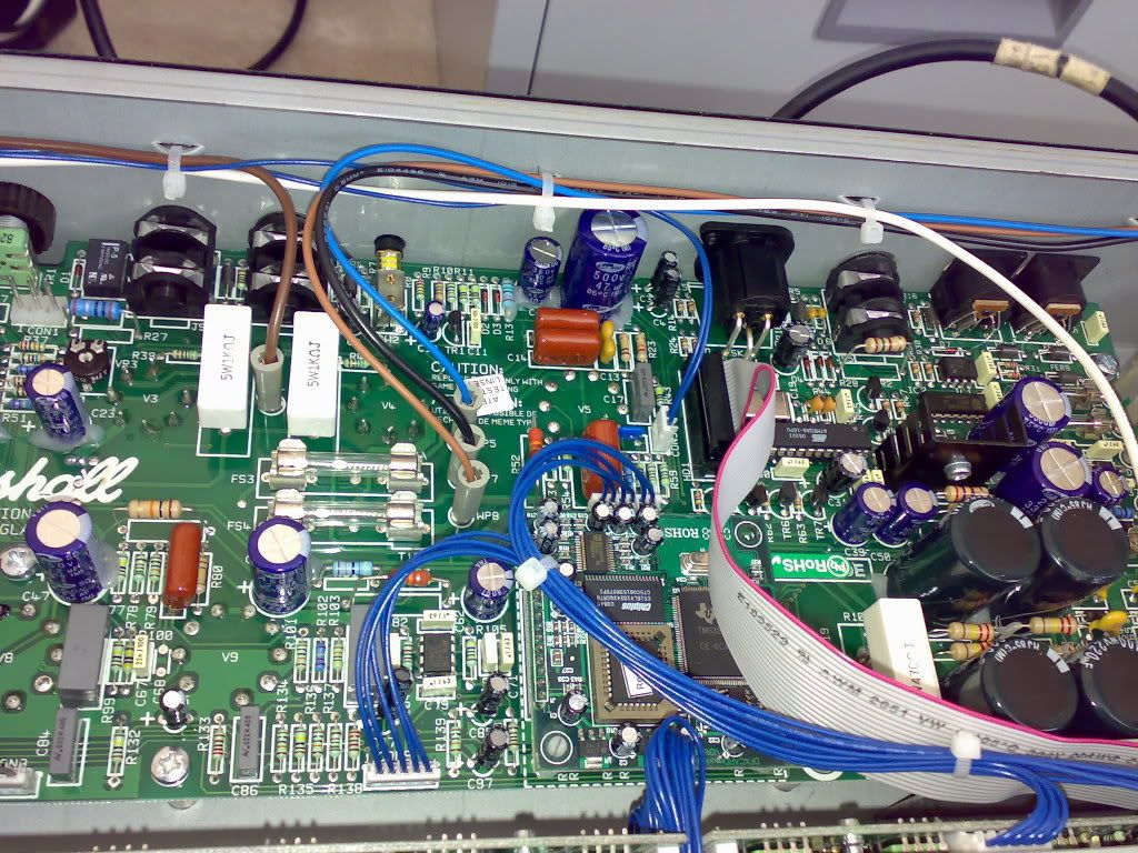
Black caps are the filter caps (the lethal scary ones), and the relay chips around here are the MIDI and Footswitching circuitry, connected via that ribbon cable to the front controls
Image

Power IEC connector at the top and the Power transformer which produces various voltages for the preamp, power amp etc.
Image

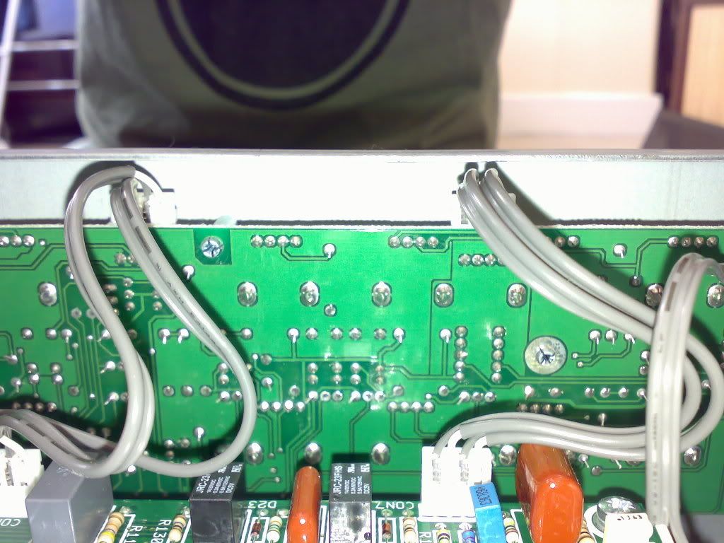
The back of the input/cotnrol board by the input side, and me, note large ground plane for lowering noise
Image

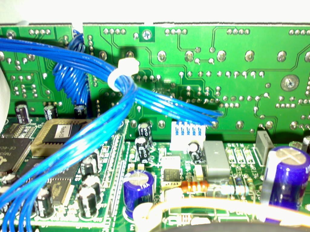
Further along the input/control board, DSP stuff on Left
Image

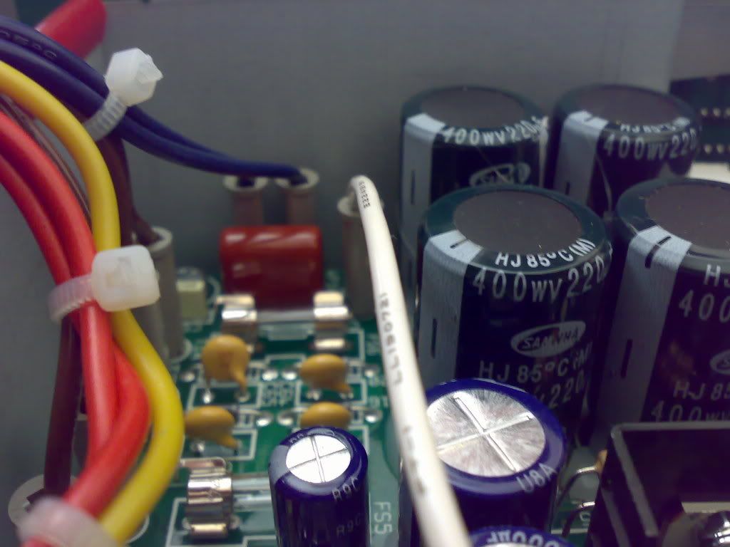
Filter Caps and another fuse from the back of the chassis
Image

The power and standby switches by the Power Transformer from the back of the chassis
Image
More Cowbell
.
.
Posts: 6206
Joined: Thu Apr 20, 2006 3:31 am
Location: Jefferson, GA

Post by More Cowbell »

sweet jesus juice.
User avatar
Justin J
.
.
Posts: 2224
Joined: Tue Aug 22, 2006 6:42 pm
Location: usa

Post by Justin J »

right now i'm making one of these:
Image

i've been running all over town trying to find parts. sorting through bins at electronic surplus stores. i even went to this cool electronic swap meet in redondo beach where a bunch of old ham radio guys get together and sell all their old crap. there's a guy there who just sells tubes. he's gonna get the hard-to-find 6k6gt tube for me $3 a piece, nos.
anyway, here's what i've got so far:
Image
so far i'm about $10-$15 into this project. the tough part is gonna be finding the transformers. i'm toying with the idea of winding my own power transformer, but i don't know how feasible that's gonna be.
User avatar
euan
partynerd!
Posts: 27589
Joined: Sat Jan 06, 2007 3:52 pm
Location: People's Republic of Irnbruikstan

Post by euan »

Image

Inside of a Tiny Terror and my crotch.
Image
euan
User avatar
Sloan
Sexy Predator
Posts: 11797
Joined: Thu Apr 20, 2006 3:02 am
Contact:

Post by Sloan »

lol.
I thought the JVM would have moar shit in it.
finboy
.
.
Posts: 3564
Joined: Fri Feb 08, 2008 3:56 am
Location: Calgary, Alberta, Canada

Post by finboy »

why is it i always feel pains of fear whenever i see whats inside electrical devices? lol
User avatar
paul_
.
.
Posts: 10306
Joined: Thu Jul 27, 2006 10:38 pm

Post by paul_ »

1973 Marshall Superbass road warrior master volume'd bright capapalooza

Image


Attack of teh Clonez

Image

The fridge-rattler (sans attenuation)
Image
Aug wrote:which one of you bastards sent me an ebay question asking if you can get teh kurdtz with that 64 mustang? :x
robertOG wrote:fran & paul are some of the original gangstas of the JS days when you'd have to say "phuck"
User avatar
Mike
I like EL34s
Posts: 39170
Joined: Thu Apr 20, 2006 8:30 am
Location: Edinburgh, Scotland
Contact:

Post by Mike »

Sloan wrote:lol.
I thought the JVM would have moar shit in it.
It's very well designed. I could probably debug it if something went wrong because it's laid out so well.
User avatar
filtercap
.
.
Posts: 493
Joined: Tue Oct 10, 2006 3:51 am
Location: the information coalmine

Post by filtercap »

Excellent stuff, everybody!

Mike -- Bravo on the photo tour. Circuit-board amps are just so.... different inside. Admit it... you were flying a tiny X-Wing model over that circuit board before you took the photos, weren't you. Stay on target.... Stay on target.... WEDGE! k-boom :) Anyway, I'm always impressed when somebody can find their way around a maze like that, especially if there are traces on both sides. The ground plane you speak of... does that mean the large open fields of copper (copper, right?) on that board in between the traces, which I take it would all be at ground potential? Dinna know that.

Euan -- Same thing, I look at those cirkit boards and wonder how you... you know... get at stuff. I forget, were you going to modify something a while back?

Bubbles -- Murmuring sexy little nothings like "maybe I'll wind my own transformer" on a public forum. This better not happen without pics. :!: You're stocking up on teh vintage parts for the reverb? What are those capacitors made of inside? (Paper/oil, foil/earwax, what?). 6k6 = stock Fender tube for these?

Paul -- The Marshall Superbass and clone -- are you collecting or doing the cloning yourself or ?
User avatar
euan
partynerd!
Posts: 27589
Joined: Sat Jan 06, 2007 3:52 pm
Location: People's Republic of Irnbruikstan

Post by euan »

I think you mean Finboy's comment there Filter. I love opening things up.

I was planning to build a tubeamp this year. But that is looking unlikely as I get my flat together.
Image
euan
User avatar
Bacchus
Whatever's handiest
Posts: 23590
Joined: Thu Apr 20, 2006 4:10 am
Location: wandering

Post by Bacchus »

I took the back off my organ the other day. There were no tubes, but stacks and stacks of circuit boards. Everything inside is brown with dust. I shall take pics at some point.
Image
User avatar
filtercap
.
.
Posts: 493
Joined: Tue Oct 10, 2006 3:51 am
Location: the information coalmine

Post by filtercap »

euan wrote:I think you mean Finboy's comment there Filter. I love opening things up.
What I meant was, I'd feel the same way looking @ your circuit board as I would looking @ Mike's: if I wanted to change something, how would I get at it to make/break connections? I'm used to the rat's-nest of wires in my own amp.
deadonkey
Sweetheart of the Rodeo
Posts: 1123
Joined: Tue Apr 18, 2006 1:34 pm
Location: Dublin - Northsoide

Post by deadonkey »

there's a hell of a lot going on in there, i wouldn't like to have to work on it. PCBs scare the crap outta me.

good job though.
everything is not going to be alright
User avatar
Mike
I like EL34s
Posts: 39170
Joined: Thu Apr 20, 2006 8:30 am
Location: Edinburgh, Scotland
Contact:

Post by Mike »

filtercap wrote:Excellent stuff, everybody!

Mike -- Bravo on the photo tour. Circuit-board amps are just so.... different inside. Admit it... you were flying a tiny X-Wing model over that circuit board before you took the photos, weren't you. Stay on target.... Stay on target.... WEDGE! k-boom :)
hahaha Absofuckinglutely. And what a Legend you are for name checking Wedge <3
filtercap wrote:Anyway, I'm always impressed when somebody can find their way around a maze like that, especially if there are traces on both sides. The ground plane you speak of... does that mean the large open fields of copper (copper, right?) on that board in between the traces, which I take it would all be at ground potential? Dinna know that.
Well it's just broad strokes, there's no released schematic but once you've seen one Marshall switcher you've seen them all ;)
Ground planing is pretty common in PCB design, the stuff you've worked on it's not necessary as you're not going to get teh crosstalk and coupling effect on handwiring or tagboards. I'm impressed by the layout and work on teh JVM, it's very complex but it's.. ordered. The designer spent a lot of time designing the way the circuit was going to be built as well as function.
User avatar
paul_
.
.
Posts: 10306
Joined: Thu Jul 27, 2006 10:38 pm

Post by paul_ »

filtercap wrote:The Marshall Superbass and clone -- are you collecting or doing the cloning yourself or ?
I found the Superbass in Guitar Center in 2002 or so for a grand. Someone had put a PPIMV and installed the knob in place of the power lamp, which was relocated to underneath one of the switches. It's an aluminium-face, but it's also handwired, which is sweet because Marshall switched to PCBs in late '73, so I got a transitional model, and one of the last handwired "plexis" ever.

The homebrew is a '67 1959slp Superlead clone, with as many parts I couldn't source myself from Metroamp filling in. I got a white headcase for it and use it more than the '73 now, it's a bit cleaner.
Aug wrote:which one of you bastards sent me an ebay question asking if you can get teh kurdtz with that 64 mustang? :x
robertOG wrote:fran & paul are some of the original gangstas of the JS days when you'd have to say "phuck"
User avatar
Mr Mustache
.
.
Posts: 651
Joined: Wed May 03, 2006 9:47 pm
Location: Norfolk, Virginia
Contact:

Post by Mr Mustache »

Here in the inside of my 1967 115 Alamo Fury Bass combo, when i bought it and changed out the auto push button switch that was screwed into the top of the amp for a regular SPST.... it's got a pair of 7868 tubes and 1 12AX7

Image
User avatar
Mike
I like EL34s
Posts: 39170
Joined: Thu Apr 20, 2006 8:30 am
Location: Edinburgh, Scotland
Contact:

Post by Mike »

Nice!
User avatar
Justin J
.
.
Posts: 2224
Joined: Tue Aug 22, 2006 6:42 pm
Location: usa

Post by Justin J »

filtercap wrote:Bubbles -- Murmuring sexy little nothings like "maybe I'll wind my own transformer" on a public forum. This better not happen without pics. :!: You're stocking up on teh vintage parts for the reverb? What are those capacitors made of inside? (Paper/oil, foil/earwax, what?). 6k6 = stock Fender tube for these?
i've got a couple of transformers that i'm trying rip apart right now. i want to see how feasible it's going to be before i commit to anything. i think i'm just gonna buy the output transformer and the choke online. maybe from weber or something.
those capacitors are vintage mainly out of necessity. i didn't go out of my way to get them. most of them are the only ones i can find with the specific values i need. and the 6k6 is stock for the reverb. the reissues and the weber kits use a 6v6.
User avatar
filtercap
.
.
Posts: 493
Joined: Tue Oct 10, 2006 3:51 am
Location: the information coalmine

Post by filtercap »

Here's the insides of the thundering Twin-o-Lux. The wiring is actually tidier than I found it. The chassis decided to Get Bent! during some previous owner's tenure. I've unbent it a little.

Image
At top left is the push-pull Master Volume knob, which used to engage a hideous distortion feature when pulled out. I changed things around so it's in "normal" gain mode when pulled out, and engages a pretty decent fat/boost of my own devising when pushed in. You can see the disconnected high-bypass cap just off to the left of the pot; I left it in place in case I change my mind.

The 7 Vibrato channel controls do their usual thing. On the other side of the Vibrato input jacks are the "Normal" channel controls. The tone stack in this channel is as close to a '61 "blonde" Twin as I could get with available parts, hence the capacitors sticking out in odd places. The Bass knob on this channel is push-pull too (pulled out in the pic). Now that I have two different input/tone-stack sets, the push-pull knob determines which set gets routed through the Vibrato channel (vib, rev, additional gain stage, and optional fat/boost) and which set gets routed through the good old dry "Normal" channel.

Just to the right of the big power transformer is the rebuilt solid-state rectifier on a rectangle of plain circuit-board. It's bracketed vertically to a couple of the transformer mounting bolts, so you're looking at it edge-on. This opens up some floor space for the small nuclear reactor you see there. It's really a plate-voltage control for the power-amp tubes.

Along the back of the chassis (bottom of the pic), starting at the left, you have the business end of the power cord, then an AC socket, ground switch, fuse, power switch, standby switch, two unusual series-wired speaker jacks that connect two separate transformer taps, variable negative-feedback control, bias balance pot, bias level pot with a "range" pot soldered back-to-back, tip-ring-sleeve vib/rev footswitch jack, reverb out, reverb in, and heater hum-balance pot.
User avatar
mewithoutus
.
.
Posts: 1246
Joined: Sun Apr 22, 2007 7:46 am
Contact:

Post by mewithoutus »

cool thread, miek.

i'll post gut shots of my ac30 today!
rich people say fuck yeah hey hey
heavium wrote:grow a bat army in my room and train them to attack when someone comes in