Project Vibro-Champ - Part 9 - DONE!

Pickups, pedals, amps, cabs, combos

Moderated By: mods

User avatar
filtercap
.
.
Posts: 493
Joined: Tue Oct 10, 2006 3:51 am
Location: the information coalmine

Project Vibro-Champ - Part 9 - DONE!

Post by filtercap »

This week on New Horizons in TL/DR....

My birthday prezzy from Madame Filtercap this year was a luvly new 10" Weber alnico speaker. Not to put too fine a point on it, it's a 3.2-ohm 20-Watt model 10A125-O. Time to make some long-awaited... er... "improvements" to my silverface Vibro Champ. Let the games begin.

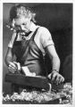
Here's the Vibro Champ with the grille and speaker removed, and the new speaker. On the old speaker you can see the alnico magnet structure. The new one is similar underneath that bell-shaped cover, but larger.
Image


Replacing the VC's 8-inch speaker with a 10-incher is not a new idea by any means. But it is challenging because some of the goodies hanging down from the chassis -- especially the output transformer and the "cap can" -- are taking up space that the speaker basket needs. Some people deal with this by mounting the new speaker off-center to the left. I didn't want to do this, though, because the particleboard grille frame is wider on that side to support the Fender badge, and the triangle of board under the badge will block part of the speaker. Why install a larger speaker and then cover it partway?

The other approach is to move the speaker =forward= in the amp by reverse-mounting it to the baffle. (In other words, mount the speaker so the back of its rim touches the baffle, not the front.) Easier said than done, because now the speaker would stick too far forwards and make it impossible to re-install the grille. The answer is to reverse-mount the speaker on a baffle-within-a-baffle, so that the speaker's front is flush with the front face of the original baffle. That moves the speaker forward about a half-inch overall -- hopefully enough to get the basket away from everything.

The outside dimension of the speaker is just a hair smaller than the height of the original baffle. So I can't just cut a hole. I'll need to remove the center of the baffle and leave two wings to mount the new baffle. I decided to make an oval hole so that I can slide the new speaker/baffle unit towards either side if I have to. I traced the outside of the speaker onto the old baffle.
Image

I left as much as possible of the old baffle to support the new baffle, along with the velcro tabs that hold the grille frame on. I cut the new baffle from plywood, with a hole just slightly larger than the inside dimension of the speaker rim. I also cut three gasket rings: two from very dense mat-board (the stuff you frame pictures with) and one from some thin double-wall cardboard that can "crush" a little bit to conform to the baffle. The gaskets help the speaker seat evenly, and they serve as spacers to get the front edge of the speaker flush with the old baffle face. Here's everything so far. (Two of the rings are glued together already.)
Image

New speaker, reverse-mounted on the new inner baffle. I trimmed the gaskets at the baffle edges so they don't hit the cabinet or the chassis.
Image

I test-fit everything with the chassis in place. The old cap can still contacted the speaker basket unless I slid the new speaker/baffle off-center. Too close for comfort. Time for my evil plan.

As part of the project, I'm replacing the filter caps with a new cap-can anyway. The can sticks down from the chassis like a vacuum tube. Its top fits up against a hole in the chassis, and tabs coming out of the top of the can are bent/soldered to the inside of the chassis to hold it in place. They use some kazillion-watt iron to do this, and it's impossible to melt all that solder again. I ground through the old tabs/solder with a Dremel tool and pulled off the old can.

Now to get myself some breathing space above the speaker, I jacked up the new cap can on some metal stand-offs. I screwed the bottoms of these through little holes I drilled on each side of the big cap-can hole. The new can has insulated "ears" with screw slots, perfect for screwing into the tops of the standoffs. Here's my exclusive, patented hi-rise cap can from inside the chassis....
Image

... and from outside. I'm holding the old can in place in the background for comparison. I gained almost an inch of extra space.
Image

Here's the new can, wired in place. The black ground wire goes from one of the four grounding tabs to one of the huge lumps of solder that was holding the old can in place.
Image

And now everything fits with the speaker centered! There's about a fingertip-worth of clearance between the cap can and the speaker. The transformer has room too, especially because one of the slots in the speaker basket sits right below it.
Image

The 5Y3 rectifier tube on the left has plenty of room over the bell cover. The original RCA 6V6 tube had a decent amount of room. The new JJ 6V6 in the photo is longer. I can just =barely= get it into the socket with the chassis in place. I might eventually slide the inner baffle to the left a half-inch to help things out. All I need to do is unscrew the baffle, slide, and screw it in again.

Front view, sans grille. It looks a little odd because I left so much of the original baffle in place. I might trim the gaskets down a bit if I want to slide things farther. (The Thundering Twin-o-Lux in the background has a baffle-in-a-baffle job too... another story. I often remove the grille when recording. Yay 70's Velcro.)
Image

It sounds great so far. The JJ 6V6 absolutely kills the old RCA tube for lows and volume. I re-installed one of the old RCA 12AX7s, and that's way better-balanced than the spiky-sounding Groove Tube I had in the preamp. The GT in the vibrato circuit is just fine. Nice vibrato.

I'll play the amp a bunch to break the speaker in a bit and get used to how it sounds. A bunch of maintenance chores and mods await. Much mirth shall ensue. Tune in later for more top-quality TL/DR right here.
Last edited by filtercap on Thu May 08, 2008 8:50 am, edited 8 times in total.
User avatar
Justin J
.
.
Posts: 2224
Joined: Tue Aug 22, 2006 6:42 pm
Location: usa

Post by Justin J »

every time you make a thread, i always find it so fascinating. but i'm way too tired to read this tonight. i'm gonna properly read this tomorrow.
User avatar
mewithoutus
.
.
Posts: 1246
Joined: Sun Apr 22, 2007 7:46 am
Contact:

Post by mewithoutus »

A+ thread.

very cool man. i bet it sounds killer.
rich people say fuck yeah hey hey
heavium wrote:grow a bat army in my room and train them to attack when someone comes in
User avatar
euan
partynerd!
Posts: 27589
Joined: Sat Jan 06, 2007 3:52 pm
Location: People's Republic of Irnbruikstan

Post by euan »

I couldn't work out what you meant buy bringing the speaker forward on a first quick scan. Then I saw the picture at the bottom. Genius.
Image
euan
User avatar
Thom
lamp
Posts: 6999
Joined: Thu Apr 20, 2006 8:23 am
Location: Exeter, UK

Post by Thom »

Great thread again.
User avatar
Justin J
.
.
Posts: 2224
Joined: Tue Aug 22, 2006 6:42 pm
Location: usa

Post by Justin J »

definitely a cool read. i might possibly have some twin reverb questions for you in the future.
User avatar
Mike
I like EL34s
Posts: 39170
Joined: Thu Apr 20, 2006 8:30 am
Location: Edinburgh, Scotland
Contact:

Post by Mike »

You make such great threads, and you came up with a brilliant solution. BRAVO!
User avatar
drasp
.
.
Posts: 220
Joined: Thu Jan 17, 2008 3:04 am
Location: St. Petersburg, FL

Post by drasp »

VERY NICE!!! **happy**

More details on the Weber cap can? I need to replace the can in my '67 Champ, but I've been lazy. Found a good source & the correct values, then lost the link & haven't bothered to re-find it. Is Weber the way to go over TAD or some of the other re-pros? I like Webers speakers (2x10"s in my Vibroverb & 1x 8" in my Champ) & I LOVE that he is in Indiana, my home state. Yeah. I'm rambling now.
User avatar
filtercap
.
.
Posts: 493
Joined: Tue Oct 10, 2006 3:51 am
Location: the information coalmine

Post by filtercap »

drasp wrote:VERY NICE!!! **happy**

More details on the Weber cap can? I need to replace the can in my '67 Champ, but I've been lazy. Found a good source & the correct values, then lost the link & haven't bothered to re-find it. Is Weber the way to go over TAD or some of the other re-pros? I like Webers speakers (2x10"s in my Vibroverb & 1x 8" in my Champ) & I LOVE that he is in Indiana, my home state. Yeah. I'm rambling now.
If Weber and Robert(original) ever join forces, the rest of us might as well give up and get used to living in the Indiana Century. :D

It looks like you already know the main knowables about cap cans. I'm not aware of one manufacturer's product sounding better than any other can of the same values. The Webers do claim to have better "isolation" than some other cans, so maybe current leak or capacitance between caps is an issue? They also say that their copper cans handle heat better than steel or aluminum. All that could well be true, but it's their sales copy so take it as such. I'd mainly look for reliability, and Weber has a good reputation for quality and customer service. Plus we saved on shipping that way. :wink:

After removing the old aluminum Mallory can, I noticed that it has two 20-uF caps and one 40-uF cap. They stamped little shapes next to the tabs and printed a key on the side to tell you which tab goes with which cap. (Weber uses numbers.)

ImageImage

Each tab goes to the positive end of a capacitor, and all the negative ends go to a common ground on the can. Grounding the can to the chassis completes the circuit.

The Vibro Champ schematic shows three 20-uF caps, and my Weber can has four 20-uF caps. I'm not sure where the Mallory's 40uF section was wired up, because I assumed they were all the same per the schematic. No problem -- I can wire up the Weber's extra section in parallel with one of the others to get 20+20=40uF if I want. I'll try this later on in the project (maybe on the first preamp stage which is the most vulnerable to noise) and see what happens.
User avatar
drasp
.
.
Posts: 220
Joined: Thu Jan 17, 2008 3:04 am
Location: St. Petersburg, FL

Post by drasp »

Awesome - thanks for the detail! :D

One of the filter caps in my can had gone bad & was replaced by a separate cap wired outside the can by a previous owner. I don't know if this is common practice or not, but it kinda' bugs me & I'd like to "do it right". Also looks (to me) like my OT has been replaced, but I don't know what was used. I have a hunch it might be an "upgrade" as this Champ has more headroom than others I've played & owned (not a great thing IMO). I'd like to see about finding out what kind of OT I've got now & what (if anything) I'd have to gain in terms of "correctness" by changing it as well.

Mine:

Image

edit - this picture isn't 100% up to date. I've re-wired with a 3-prong power cord & removed the "death cap".
User avatar
filtercap
.
.
Posts: 493
Joined: Tue Oct 10, 2006 3:51 am
Location: the information coalmine

Post by filtercap »

drasp wrote:Awesome - thanks for the detail! :D

One of the filter caps in my can had gone bad & was replaced by a separate cap wired outside the can by a previous owner. I don't know if this is common practice or not, but it kinda' bugs me & I'd like to "do it right". Also looks (to me) like my OT has been replaced, but I don't know what was used. I have a hunch it might be an "upgrade" as this Champ has more headroom than others I've played & owned (not a great thing IMO). I'd like to see about finding out what kind of OT I've got now & what (if anything) I'd have to gain in terms of "correctness" by changing it as well.
So tidy inside! It helps that you don't have the extra 2 knobs, extra tube, and footswitch jack that the Vibro has cluttering it up. Aerial guts-photo coming soon.

I've heard of people putting Fender Princeton transformers on these, and also a rumor that Fender started putting Princeton transformers on (Vibro)Champs at some point.... supposedly throwing the output tube voltages out of wack with whatever cosmic harmony they were in previously. Dunno how true that might be. If there's a number stamped on your transformer, you may be able to research it.
User avatar
filtercap
.
.
Posts: 493
Joined: Tue Oct 10, 2006 3:51 am
Location: the information coalmine

Project Vibro Champ -- Part 2

Post by filtercap »

PART 2 -- Where Am I?

Time to take a look around before I start soldering. I removed the chassis from the amp and set it up on a stand-bracket-deal I made from scrap lumber to hold my Twin chassis. The cabinet is back-to-back with the chassis so I can keep the speaker plugged in.
Image

Here's a shot of the insides. You can click it to see a bigger one if the words are hard to read. The only thing I've changed so far is that capacitor can.
Image

One thing I noticed after switching the amp on was a low hum that's present even when the volume is turned down to 0. I plugged in a Jazz Bass (it was handiest at the moment) with all its dials turned down. Same hum. I swapped the old cap can back in -- same hum that way. Back to the new can again.

I switched on my Twin, turned the volume knobs down all the way, plugged in the silent bass, and cranked the master volume up to 10. Much bigger amp, but much much more hum. Maybe it's not so bad, but I'll want to see if I can make it quieter later on. I have some ideas to try.

I do recall something similar when working on the Twin. With the chassis out in the open, it isn't shielded from above by the sheet of metal in the cab and tends to be noisier anyway. We'll see....

I tested some voltages, and was really surprised. The schematic shows 355 volts coming out of the rectifier, and 342 volts at the plate of the power tube. The amp is cranking out 410 and 397 volts in those two places -- 55 volts higher! Other points in the amp are high by similar proportions. 241 volts at the preamp tube plates for example, vs. 200-205 volts in the schematic.

The schematic I have is from the "blackface" era. The silverface Vibro Champs have an identical layout, so it's a decent reference. After some Web searching, it turns out that the voltages I'm seeing are typical for the silverface VC's. So maybe they did start building these with Princeton transformers after all.

The cathode resistor on the 6V6 measures 520 ohms, and it was dropping 25.6 volts to ground. So the current across it was .049 amps. The plate-to-cathode voltage was about 371 volts, so that comes out to a plate dissipation of over 18 ekwatts. I mean 18 Watts. Extremely hot for a 6V6 tube, but apparently intentional on Fender's part. I found a bunch of places on the Web that talk about this, and some places recommend only particular tubes like the new JJ's that can handle it.

I put the old RCA 6V6 back in. That reduced the low hum, but that's because the tube puts out so much less volume overall. Meanwhile, the voltage at the rectifier shot up to 458! I'm not doing that anymore. Back to the JJ. The filter caps are only rated for 450 volts. I'm amazed the old can even worked after so many years in there, and not surprised that the RCA 6V6 is so small-sounding. Maybe it's been slowly giving up.

With the voltage that high, it does make sense that the amp sounds pretty clean, tight, & responsive with the JJ 6V6 in there (partly due to the new speaker, no doubt). I'll be trying a couple things to bring the voltage down a bit and/or relax the bias of the power tube to get it closer to what's supposed to be its range. This may get a bit more compression going too, which I'd like.

One final discovery. There's a small capacitor on the power tube, going from the grid to the cathode.
Image

This is probably one of those silverface things I've heard about. It was the 70's and they had to ward off hostile vibrations caused by bad CBS karma or something. There's another thing to experiment with. I mean the cap, not the karma. More later.
dodgedartdave
.
.
Posts: 904
Joined: Fri Apr 21, 2006 8:12 pm

Post by dodgedartdave »

I like your monkey avatar! :lol:
User avatar
drasp
.
.
Posts: 220
Joined: Thu Jan 17, 2008 3:04 am
Location: St. Petersburg, FL

Re: Project Vibro Champ -- Part 2

Post by drasp »

filtercap wrote:Image
Howzabout putting this one up @ 1280x960 so's it can live on my desktop? :lol:
User avatar
Mike
I like EL34s
Posts: 39170
Joined: Thu Apr 20, 2006 8:30 am
Location: Edinburgh, Scotland
Contact:

Post by Mike »

Awesome Update!

hahah @ wormhole and "18 ekwatts". Cool exploration and walkthrough. I do the same thing with always having a load on stuff, it's the only safe way.

nice jig.
User avatar
filtercap
.
.
Posts: 493
Joined: Tue Oct 10, 2006 3:51 am
Location: the information coalmine

Project Vibro Champ -- part 3

Post by filtercap »

PART 3 -- "It's a bypass. You've got to build bypasses."

Next up, changing the bypass capacitors. This is sort of routine maintenance, "routine" meaning once every decade or so. Like the filter capacitors in the can, the bypass caps are electrolytic and will eventually dry up inside. When this happens, they may stop working altogether, or else start leaking DC current, which they aren't supposed to do. This amp was made in 1978, so if these caps are original -- which they may well be -- they're past-due for a change.

If you're into this sort of thing, here's some background blather on what these bypass capacitors are doing, at least as far as I understand it:
► Show Spoiler
I replaced the amp's four bypass caps with new ones. Compare to the chassis pic I posted earlier. I've read that heat from the cathode resistors can gradually cook the bypass caps, so I cut the leads long to "fly" them above the tagboard with some air space between them and their resistors.

Image

I started by removing the old bypass cap from the first stage of the power amp. With the cap gone, I switched on and played through the amp. It's a decent sound, maybe a little compressed but hard to tell. Then I switched off, soldered in the new cap, and tried again. The bass end of the guitar sound seemed a lot fuller and better balanced with the highs. I unsoldered one end of the new capacitor to take it out of the circuit... tested again... reconnected the new cap... tested again. Yep, a bigger sound with the capacitor in place. Louder? Maybe slightly. Better than the original? Hard to tell, unless I set up an A/B circuit, which I'm too impatient to do!

Then I went ahead and put the other three new caps in place. No doubt about it now, the amp sounded both bigger and louder. It's still a bright, detailed amp, but it seems to have plenty of bass to round things out. I didn't expect that much of an improvement, so it was a nice surprise. It could be that one of the other bypass caps had cut out long ago, leaving the amp quieter and thinner-sounding. This may well have been the cap on the power tube, which by design is run at the absolute top end of its voltage rating. More on that later.

I could (should?) leave well enough alone here, but there are some other things I want to try first. They may be improvements, take the sound in the wrong direction, or make no real difference at all. We'll see......
Last edited by filtercap on Thu Apr 17, 2008 5:33 pm, edited 1 time in total.
User avatar
Ninja Mike 808
.
.
Posts: 1643
Joined: Mon Jan 14, 2008 10:06 pm
Location: DFW
Contact:

Post by Ninja Mike 808 »

Dopeness. Quick question, how do you like it bein' point to point? I read this article talkin' all about how ptp was waaaaaaaaaaaay better than using a PCB, but I chalk it up to nonsense.
User avatar
drasp
.
.
Posts: 220
Joined: Thu Jan 17, 2008 3:04 am
Location: St. Petersburg, FL

Post by drasp »

PCB vs. Point to Point vs. Turret Boards = all different. There is no real "good" or "bad", only gross generalizations. It takes a LOT more time & money to build an amp w/o any PCBs & as such the only stuff you see today with PtP or turret boards is high-end, boutique or re-issue/replica. There are pros and cons of all 3 ways of building, but I actually dig a GOOD PCB amp. In a GOOD PCB amp the circuit designer is able to reduce noise, cost & make the amp to amp consistency much better. Way less likely to have a "sweet" example of a PCB amp and a "lousy" one. Some folks argue that hand-wired amps are superior b/c they're easier to work on which isn't necessarily true either. If you know what you're doing with a soldering iron, removing through-mount components from a high quality board is nothing. On a cheap board with surface mount components and ICs THAT is where you get into trouble and start throwing away entire boards as an only option. Really, this is a long standing argument, some folks need to see the guts of their gear laid out on a turret board to feel sexy & that's okay - a lot of the best amps ever made are built this way. Just worth keeping it in perspective and knowing the WHYS of the arguments on both sides. . .
User avatar
filtercap
.
.
Posts: 493
Joined: Tue Oct 10, 2006 3:51 am
Location: the information coalmine

Post by filtercap »

For purposes of experimenting with an existing circuit and making modifications, I find point-to-point is great. If you want to lift one end of a component to see what happens, or insert a resistor in the junction between two other components, or re-route what's going to each terminal of a pot, I'd say you can do this more easily and less destructively with point-to-point.

But keep in mind that PTP is where I've committed most of my crimes, so I don't know the tricks for slick & easy PCB modding and I can't compare them well from personal experience. If I were more into modifying pedals, I'd likely have more to say about the good & bad points of PCB. I must say that if I wanted to build a kit and do it quickly (and I have), PCB is the way to go.

Drasp makes some very good points about the two.
User avatar
Sloan
Sexy Predator
Posts: 11797
Joined: Thu Apr 20, 2006 3:02 am
Contact:

Post by Sloan »

This is seriously probably the most text-per-post thread I've ever witnessed during my internets. Keep up the awesome!