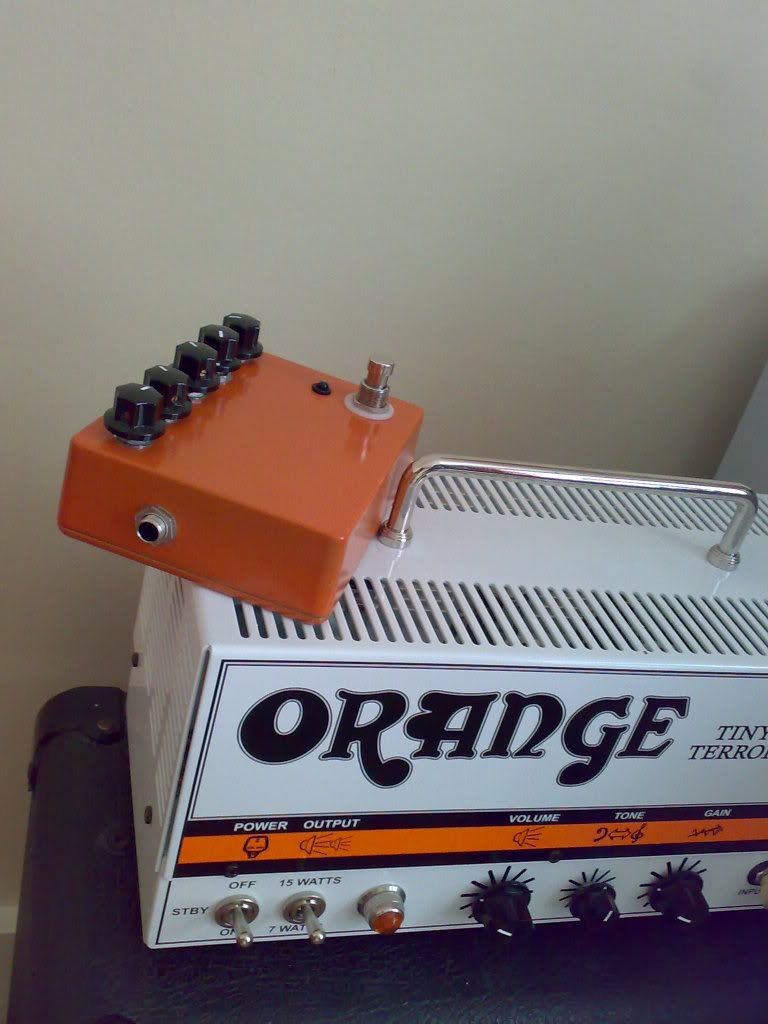
OLC Orange Peel Build (done)
Moderated By: mods


Doog wrote:I remember reading in the PDF manual that the pedal doesn't have a set polarity? I.e, it'll work either way round. NO idea how this is possible

Replace "AC in" with "DC in, either polarity", and "DC in" (?) with "DC out".
Although this allows you to use either polarity, you lose two diode drops in voltage. Using Schottky barrier diodes like the >>1N5817<<, 17p >>at Maplin<<, you could keep this down to under 0.7V at 100mA. Germanium diodes have a slightly lower forward drop but it's difficult to find a germanium diode with a useful current capacity these days.
-
Ninja Mike 808

- .

- Posts: 1643
- Joined: Mon Jan 14, 2008 10:06 pm
- Location: DFW
- Contact:
-
Mike

- I like EL34s
- Posts: 39170
- Joined: Thu Apr 20, 2006 8:30 am
- Location: Edinburgh, Scotland
- Contact:
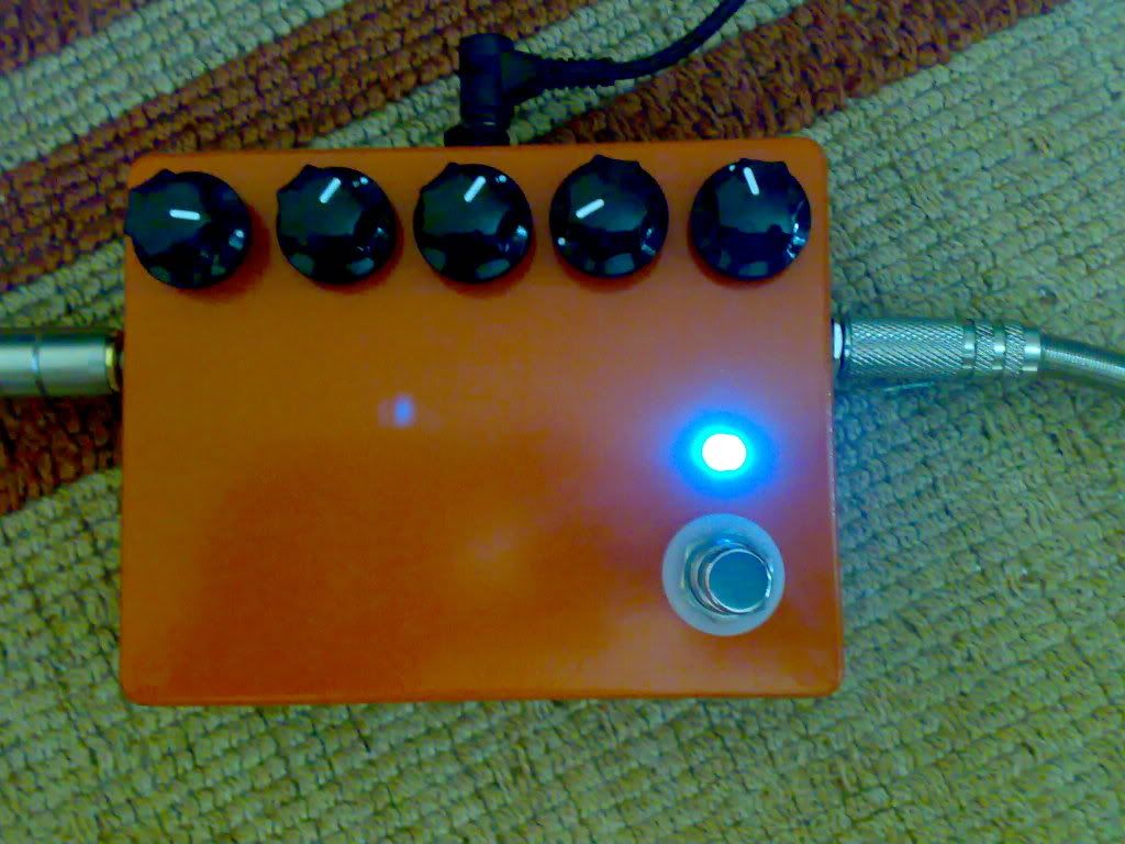
Fixed the pots, but realised some of the wires were getting duff from all the in and out of the case action, so after replacing the volume pot wiring, then the gain, then teh treble, and then the bass.. I basically redid all the pot wiring (and routed them all under the board so it's much tidier now.) and now it's quiet as a mouse and sounds great. Need to see if I can get some rub-on transfers for lettering today, or I'll just scrawl on it. Going to replace the input jack with a switchcraft like I did the output. The holes are too large for these cliff jacks really and I hate Cliff jacks. You have to offset the plastic from the hole inside to hold it firm since the diameter of the drilled hold exceeds the plastic of the cliff jack.
No worries, will get a new jack and sort it and post final gut shots then.
No worries, will get a new jack and sort it and post final gut shots then.
-
Mike
- I like EL34s
- Posts: 39170
- Joined: Thu Apr 20, 2006 8:30 am
- Location: Edinburgh, Scotland
- Contact:
I don't like using stranded wire is also something I've learnt. When you're moving the wires like I did on the pots the insulation can get really hot in the unsoldering/removing process and peel back, I think I lost the integrity of the the wires then. I use solid core on all my Saltboosters now and all the replacement wiring I did on this was solid-core, and it all works a charm. Like I said in the other thread, I also found a lifted PCB trace so had to make a jumper to ground from one of the caps in the bass control filter stage, it was causing a large unstoppable bassy hum. Took a while to find the bastard. The build is MUCH neater with the pot wiring under the board and only the FAC wiring on top. I also removed the battery clip, I'll never use it.
BTW I got some Neutrik open style jacks on the way from Banzai, I saw them and thought of you.
BTW I got some Neutrik open style jacks on the way from Banzai, I saw them and thought of you.
-
euan
- partynerd!
- Posts: 27589
- Joined: Sat Jan 06, 2007 3:52 pm
- Location: People's Republic of Irnbruikstan
I would have Neutrik build me a house if I could. That shit will survive a nuclear explosion.
I was going to boost to Halfords and get some paint for my boxes+Woolcaster (which I am going to finish) but the routes to either Halfords within 5 miles of me either take me through bandit country or exits from motorways. Do not want to be doing that on my bike.
I was going to boost to Halfords and get some paint for my boxes+Woolcaster (which I am going to finish) but the routes to either Halfords within 5 miles of me either take me through bandit country or exits from motorways. Do not want to be doing that on my bike.

euan
-
Ninja Mike 808
- .
- Posts: 1643
- Joined: Mon Jan 14, 2008 10:06 pm
- Location: DFW
- Contact:
Looks pretty good. Reminds me of the color we used to use, actually, haha.
Yea, I hate when my wires start to peel back. When i build, I usually get the thing workin' with a little bit of slack and then tighten everything up. I've also been pondering whether or not to just lay some hot glue or somethin'...
Yea, I hate when my wires start to peel back. When i build, I usually get the thing workin' with a little bit of slack and then tighten everything up. I've also been pondering whether or not to just lay some hot glue or somethin'...
-
Ninja Mike 808
- .
- Posts: 1643
- Joined: Mon Jan 14, 2008 10:06 pm
- Location: DFW
- Contact:
-
Ninja Mike 808
- .
- Posts: 1643
- Joined: Mon Jan 14, 2008 10:06 pm
- Location: DFW
- Contact: