Mike's Pedal Thread
Moderated By: mods
- Mike
- I like EL34s
- Posts: 39170
- Joined: Thu Apr 20, 2006 8:30 am
- Location: Edinburgh, Scotland
- Contact:
Projects in the works:
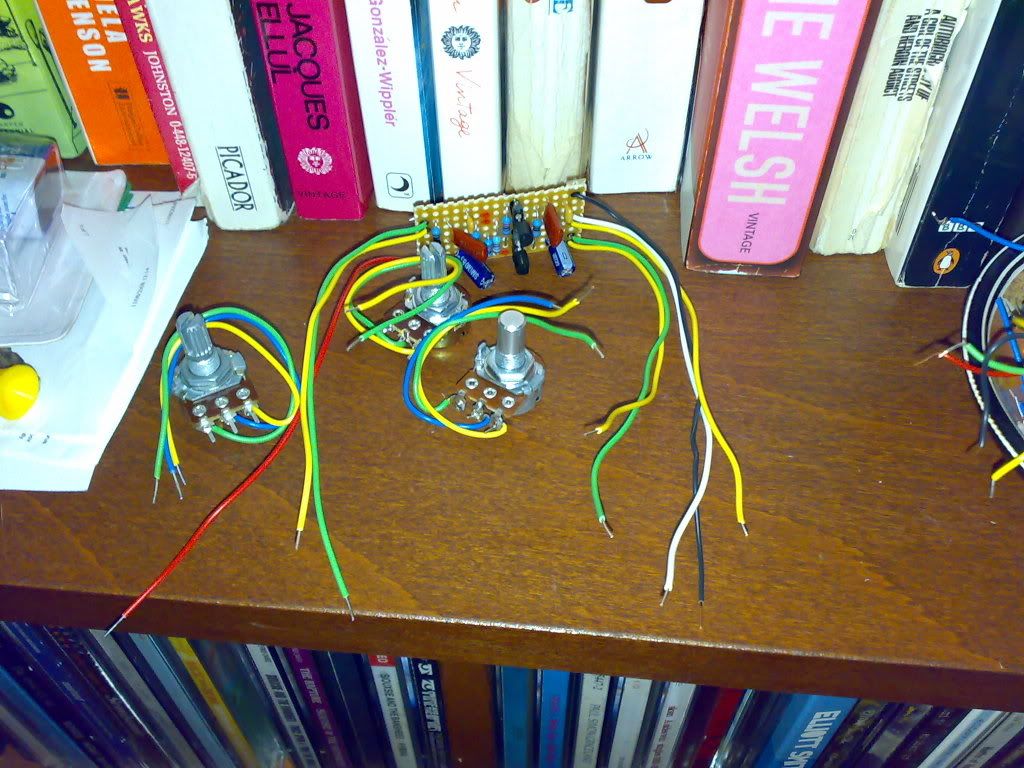
St. Jimmy - Coupletones Fuzz
- with aggressively offensive decal'd control names.
- Metallic Red paint, Blue LED.
- $90 shipped (I believe I said $80-$100? correct me if I'm wrong)
- board built, case marked up and will be drilled on Tuesday

Zaphod - Harmonic Perculator with Tone control
- Added tone control
- Metallic Blue
- £60 shipped
- will mark up case tonight and drill on Tuesday.
Fran - switch replacement in Marshall GV-2 Guv'nor Plus
St. Jimmy - Coupletones Fuzz
- with aggressively offensive decal'd control names.
- Metallic Red paint, Blue LED.
- $90 shipped (I believe I said $80-$100? correct me if I'm wrong)
- board built, case marked up and will be drilled on Tuesday

Zaphod - Harmonic Perculator with Tone control
- Added tone control
- Metallic Blue
- £60 shipped
- will mark up case tonight and drill on Tuesday.
Fran - switch replacement in Marshall GV-2 Guv'nor Plus
-
JamesSmann
- .

- Posts: 11873
- Joined: Thu Apr 20, 2006 10:15 pm
you did say 80-100, so 90 is just peachy keen with me, good sir!Mike wrote:Right so Projects in the works:
St. Jimmy - Coupletones Fuzz with aggressively offensive decal'd control names. Metallic Red paint, Blue LED. - $90 shipped (I believe I said $80-$100? correct me if I'm wrong)
and oh yeah, lol to the Coupletones Fuzz with Aggresively offensfive decal'd control names.
- Mike
- I like EL34s
- Posts: 39170
- Joined: Thu Apr 20, 2006 8:30 am
- Location: Edinburgh, Scotland
- Contact:
Projects in the works:
St. Jimmy - Coupletones Fuzz
- with aggressively offensive decal'd control names.
- Metallic Red paint, Blue LED.
- $90 shipped (I believe I said $80-$100? correct me if I'm wrong)
- board built, case marked up and will be drilled on Tuesday
Zaphod - Harmonic Perculator with Tone control
- Added tone control
- Metallic Blue
- £60 shipped
- will mark up case tonight and drill on Tuesday.
Richard Zinsmann (non shortscaler)
- Green Big Muff with battery power
- Metallic Green with Green LED
- $150 shipped
Fran - switch replacement in Marshall GV-2 Guv'nor Plus
-
JamesSmann
- .

- Posts: 11873
- Joined: Thu Apr 20, 2006 10:15 pm
- timhulio
- Redheaded Stepchild
- Posts: 4693
- Joined: Thu Apr 20, 2006 10:06 am
- Location: London, UK
- Contact:
Good plan. I was planning on putting teh clean boost before the main circuit, but that will work better. The first one of these I've made is almost done. Re. loudness, I figured lots of people will just use it with both controls up full, so for this first one it can do without extra boosts.Mike wrote:I may put a booster output stage in also if it's not loud enough.
- Mike
- I like EL34s
- Posts: 39170
- Joined: Thu Apr 20, 2006 8:30 am
- Location: Edinburgh, Scotland
- Contact:
timhulio wrote:Good plan. I was planning on putting teh clean boost before the main circuit, but that will work better. The first one of these I've made is almost done. Re. loudness, I figured lots of people will just use it with both controls up full, so for this first one it can do without extra boosts.Mike wrote:I may put a booster output stage in also if it's not loud enough.
A boost before will most likely just saturate the gain stage, so you'll just have the one gain setting.
I was going to just through a Saltbooster stage in after the diodes.
Looks like there is a mistake in your layout now I look at it:

I think the Diodes should be clipping to and from ground from the end of C6.
And presumably R6 should be from that track to the Output pot.
Can you link me to the schematic you used?


