Peavey Windsor Project [Clipz + Pix]
Moderated By: mods
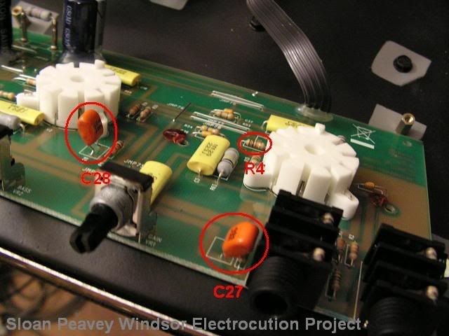
I have removed C27, and C28. These are cathode resister bypass capacitors (just like C5), they basically let more signal pass by the cathode resistor and into the next gain stage, therefore contributing to higher gain. I definitely noticed a difference this time, the gain was lowered a bit, but it still doesn't really "clean up", still kinda gritty. Also, note that all this so far, is with the master WAY WAY down, so this shit may actually be working at practice/gig volumes. haha.
Changed R4 (1K) to a 10K.
This is the cathode resistor on the second gain stage (second half of the first 12ax7).
I think this made an "improvement" in the cleans so far, the preamp gain knob stays clean until about 12 o'clock now and the clean seems to be more natural without the 'grit' that was there previously.
Ok, I replaced R53, with a higher value 1M resistor.
It cleaned up the amp, but it wasn't very responsive, it just felt like i had the volume control way down, kinda lame.
Next, I returned it to the stock configuration to try different methods.
1. Bypassed the V2 voltage divider completely and ran the two gain stages into each other with nothing between. Didn't seem to do too much.
2. Bypassed the entire second half of V2, the fourth and final gain stage.
3. Bypassed everything between V1a and V2b so it was only using two gain stages. This dropped the volume way to low for the entire amp, i had the master and pre-gain cranked and this shit was super low.
No results I've really liked yet. I'm trying to find a more dynamic sound, I think I might be taking the wrong approach, but I'm learning a lot!
HLYSHT.
I kinda got it!
I bypassed the first 12ax7's voltage divider and BAM, fucking amazing clean sounds, i can't even get it to break up or anything. Sounds really great.
There's a bit of noise, and it's not really high volume at all, so I'm gonna try to figure out how to deal with those problems, then SWITCH TIME Y'ALL.
- gaybear
- Inventor of the Blues
- Posts: 9697
- Joined: Thu Apr 20, 2006 10:52 pm
- Location: hard corvallis, oregon
- Contact:
this is fun to follow. i'm way to scared too mess with anything.
Last edited by gaybear on Sat Mar 07, 2009 3:17 am, edited 1 time in total.
plopswagon wrote: Drunk and disorderly conduct is the cradle of democracy.
damn. I didn't really get anywhere since the last "discovery". It sounded fucking awesome clean, but was noisy and wasn't loud enough.
I'm not sure wtf is going on with the inputs. I noticed a difference, but also in the JCM800 schematic, the first gain stage doesn't even connect to the second, shit's WHACK Y'ALL.
well, I searched for schematics and immediately found that sloan already posted them over here http://www.diyaudio.com/forums/showthre ... did=115439
heheh
heheh
yea.... true. going to study it a bit more and see if I can figure out what the heck is up with that.Sloan wrote:I'm not sure wtf is going on with the inputs. I noticed a difference, but also in the JCM800 schematic, the first gain stage doesn't even connect to the second, shit's WHACK Y'ALL.
cogito ergo sum...thing or other...
FUCK YEAH BROS!!!!
I just did almost exactly what I was looking for!!!
It's so fucking easy I can't believe it.
See that 1Meg resistor on the inputs?
Just take a 10k resistor and 470p capacitor, use them in parallel and put it in place of that 1meg resistor.
THIS SHIT IS AMAZING. It doesn't have all the over-the-top gain, but definitely in the AC/DC RIFFZONE, but it can be cleaned up with the guitar volume and when you crank the master on the amp, and turn the pre down, it's so fucking clean and sounds amazing. i can't believe it.
- Mike
- I like EL34s
- Posts: 39170
- Joined: Thu Apr 20, 2006 8:30 am
- Location: Edinburgh, Scotland
- Contact:
It does. It connects via the low gain input (whether it is used or not). You can see C3 coupling the first gain stage output to the low gain input which then connects to the second gain stage. When you connect the jack to the low gain input, the signal enters the second gain stage through R4/C5. If you connect to the high gain input, it goes through the first stage, out through C3 and then into the second stage via R4/C5. It's slightly confusing the way the schematic is drawn, but just think of the low input as a way of tapping in after that first gain stage.Sloan wrote:damn. I didn't really get anywhere since the last "discovery". It sounded fucking awesome clean, but was noisy and wasn't loud enough.
I'm not sure wtf is going on with the inputs. I noticed a difference, but also in the JCM800 schematic, the first gain stage doesn't even connect to the second, shit's WHACK Y'ALL.
Congrats on sorting out the amp, I'm made up for you, oh and solder that Cap to the resistor you twisted together, solder the points where you twisted either side of the resistor for a permanent connection.
I got the two different resistors i have hooked into a toggle switch so i can switch between them. just testing it. seems to work ok. this amp has a switchable FX LOOP, so I may take the relay out of it (since I don't have a spare right now) and hook it up to my "mod" so it can be switched at the same time the BOOST is....
I can't find a schematic for the Windsor Studio, but as far as I can tell from reading the specs, it's a little different.DuoSonicBoy wrote:Do you think the same thing would apply to the Windsor Studio?
I worked all night to get my "mod" to be switchable in tandem with the BOOST function. I thought for sure the switch made the relay for the BOOST activate and switched it, but it turns out both the relays in this amp are designed to turn on when the amp is powered up and they don't switch! I tested them both with a multimeter to make sure, and they don't do anything! Not sure exactly what the point is. I couldn't figure out a way to have the BOOST switch also be a voltage switch for the relay I hooked up for my "mod". Back to the drawing board y'all....
So right now, I just have a toggle switch hanging out the front of the amp so I can test it at high volume later today.