I just need to know the signal path from the pickup to the volume pot when the switch is in the 'neck' or 'muddy' position.
ie, are the 3.3k resistor and 50nf cap in the signal path, or a byway.
What'd be rilly great is if someone could colour this diagram for the correct position:
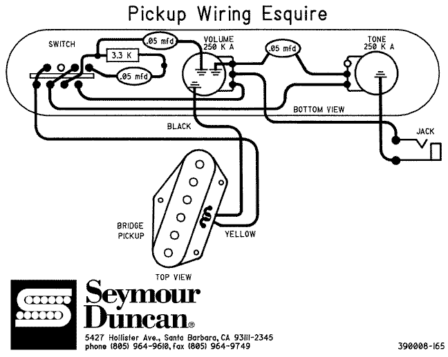
Anyone understand how tele/esquire 3-way switch works?
Moderated By: mods
Up- is muddy-like real bassy supposedly.
Middle- is standard telecaster bridge vol and tone.
Down- Trebley
one of them the tone does something i haven't played one in a while to remember fully but this is the gist of it.
EDIT- Product description states:
* Position 1. Volume Control, (Dark Vintage Circuit), No Tone Control
* Position 2. Volume Control with Cap. and Tone Control with Cap.
* Position 3. Volume Control Only No Cap. , No Tone Control
- timhulio
- Redheaded Stepchild
- Posts: 4693
- Joined: Thu Apr 20, 2006 10:06 am
- Location: London, UK
- Contact:
Okay I think I figured it.
I've wired it up (I believe) correctly- the path being:
pickup -> 3.3k resistor -> 50nf cap ->vol pot
The other 50nf cap goes before the resistor to ground.
I essentially wanted a more usable 'muddy' setting on the Hagstrom II tone switch, and figured the esquire one would do just fine.
I've wired it up (I believe) correctly- the path being:
pickup -> 3.3k resistor -> 50nf cap ->vol pot
The other 50nf cap goes before the resistor to ground.
I essentially wanted a more usable 'muddy' setting on the Hagstrom II tone switch, and figured the esquire one would do just fine.
- timhulio
- Redheaded Stepchild
- Posts: 4693
- Joined: Thu Apr 20, 2006 10:06 am
- Location: London, UK
- Contact:
Virtually no-one knows how these switches work. I crossposted this shit on TGP, OSG and FDP, the latter coming up trumps:
pickup -> 50nf cap -> resistor -> vol pot
With the 50nf cap to ground after the resistor.
Why does it sound fine then?
Which means I've got my wiring exactly backwards, and it should go:Te 52 from FDP Forum wrote:In the diagram you linked, number the top row of contacts on the switch 1,2,3,4 left to right. Number the bottom row of contacts 5,6,7,8 left to right. When the switch is in the "mud" position, 1 is connected to 4, and 7 is connected to 8.
So if you just draw in jumpers between those contacts, you have the electrical connectivity of the circuit in that position.
pickup -> 50nf cap -> resistor -> vol pot
With the 50nf cap to ground after the resistor.
Why does it sound fine then?
- ellengtrgrl
- .
- Posts: 154
- Joined: Mon Mar 30, 2009 6:24 pm
- Location: Greenfield, WI
That's due to the fact that the switches seymour duncan recommends for it's wiring scheme may be different from the switch you're using. When I replaced the crappy selector switch in my Squier Tele, I ended up realizing this the hard way, due to the fact that my replacement switch was an Allparts switch, the switching scheme didn't behave itself. OK, let's try it like this. I'm going to sort of graphically show what the switch pins should look like.
2 4 6 8
1 3 5 7
Pin #8 is the closest to the tone control. Pin #1 is what the pickup's hot lead is wired to. The pickup's ground is soldered to the volume pot's can. For the tone control + bass capacitors to be activated per the Seymour Duncan wiring diagram in what is normally the neck position of a Telecaster, you will need this:
Pin #1 will need to be wired to Pin #8 (which is where the .05 microfarad capacitor + 3.3 kOhm riseistor is also wired to), either via a jumper wire, or if your selector switch has it, via a jumper to Pin # 2, and metal strips that connect pin # 2 to Pin # 8.
Try that and see what you get.
ah yea, I was looking at this diagram I have in a magazine, that SD one, is kinda weird. I think I've figured it out though, it's really not that difficult when you think about it in normal electronics terms. it's a DP3T switch. using that fellow's numbers, 1 and 8 are the poles. Throw one is 2 and 5, throw two is 3 and 6, throw three is 4 and 7.timhulio wrote:Virtually no-one knows how these switches work. I crossposted this shit on TGP, OSG and FDP, the latter coming up trumps:
Te 52 from FDP Forum wrote:In the diagram you linked, number the top row of contacts on the switch 1,2,3,4 left to right. Number the bottom row of contacts 5,6,7,8 left to right. When the switch is in the "mud" position, 1 is connected to 4, and 7 is connected to 8.
So if you just draw in jumpers between those contacts, you have the electrical connectivity of the circuit in that position.
cogito ergo sum...thing or other...