

I'd really like to be able to keep a designated channel switched velcro'd to my pedalboard. I have a Bugera V55HD and the cable going out of the footswitch is soldered on. On the back it says 'for the Bugera footswitch only', or something to that effect. My question is: how much can the circuitry of footswitches, Can I purchase, make one that will work? It has a switch for reverb and the channel switch. Any BYOC kits I can buy or something? I'm relatively handy with a soldering iron, so making one is a possibility.
Eh?
Amp Footswitches
Moderated By: mods


Well it's soldered in as stated and the cable going out has the two stripes on the tip, which to the best of my knowledge means stereo. (noobery)chisa wrote:probably, is it a stereo jackcobascis wrote:2.chisa wrote:is it a one button?
If I took it apart could the pedal crazy shortscalers write out a schematic based on what they saw, that I could then copy into a new enclosure?
yeah, stereo jack. not too difficult to replicate. give us a pic of the internals,.cobascis wrote:Well it's soldered in as stated and the cable going out has the two stripes on the tip, which to the best of my knowledge means stereo. (noobery)chisa wrote:probably, is it a stereo jackcobascis wrote: 2.
If I took it apart could the pedal crazy shortscalers write out a schematic based on what they saw, that I could then copy into a new enclosure?
I unscrewed them, but 2 things are still holding it up, they go up into the footswitch area.when I pull down there is resistance like a rubber band.chisa wrote:yeah, just be carefulcobascis wrote:I just took it apart, all I can see is a blue lil' circuit board, but its facing up so I can't see any of the guts. It has 2 screws, unscrew em'?
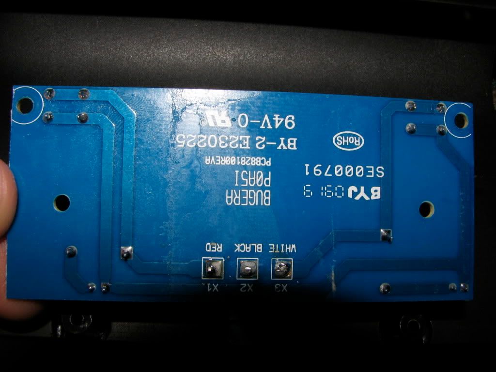
IE I have no conceiveable way of taking the board off. I assume pictures of the solder points on the back won't help..
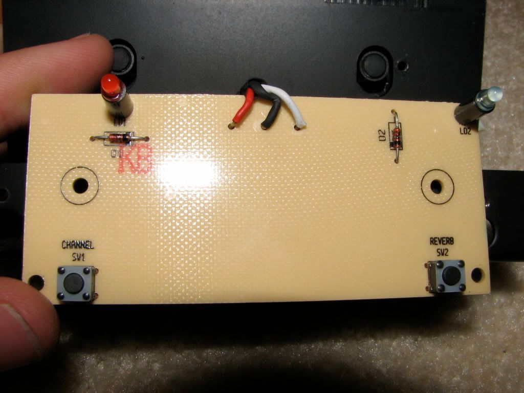


Huh, they look like small resistors, what's the difference? On one of the diodes it says 55c, near impossible to read, though.NickS wrote:Can you read what it says on the diodes (not resistors)? I'm wondering whether they are ordinary diodes or Zener diodes.
So how can I wire this up? I need an enclosure, a stereo jack, 2 diodes (what kind/value??) and 2 foot switches of some kind.


You're completely remaking this pedal?
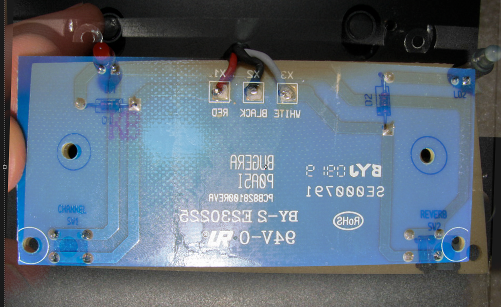
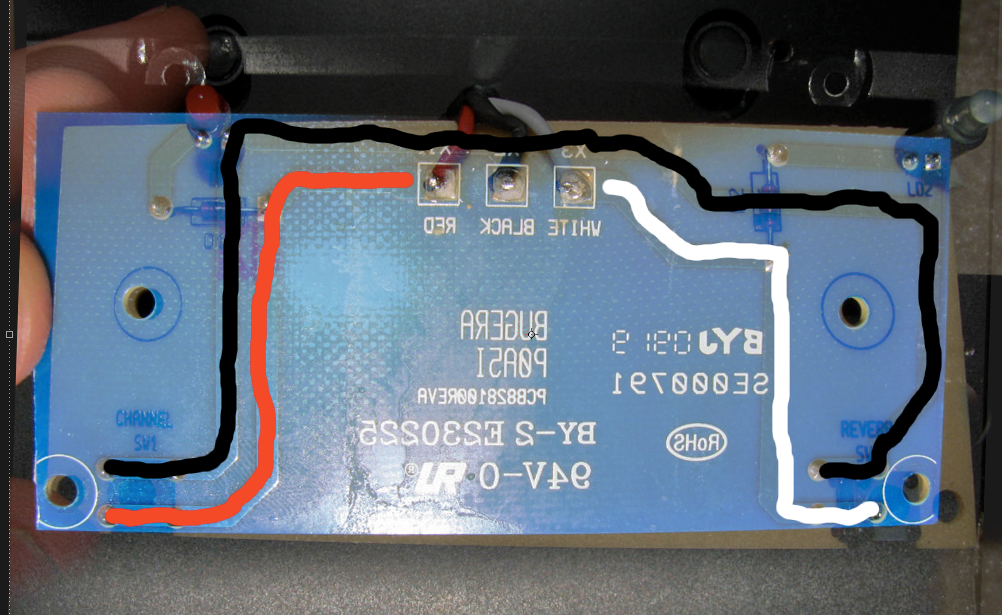
couldn't you just install a stereo jack by connecting the black to the sleeve, red to tip and white to ring. Then use it in conjunction with a stereo cable (perhaps made out of the excess cable that is connected to the board). Although, I couldn't tell you if the red to tip & white to ring will give you the correct switching, the way the pedal works. If you try it, and it's backwards, then have red to ring and white to tip. If we could see the jack part + wires leading to it, it'd help but I suspect it's completely enclosed.
I think the diodes are zeners with a small wattage, google suggests .5w. They seem to be the source of powering the LEDs after getting a signal from the amp by means of the black wire.
edit: datasheet?
OK, so they are zener diodes, that makes sense - we need to know what value though, so below the 55C there should be more info, like "3v3" or whatever, which is the clamp voltage of the zener.cobascis wrote:Can someone sketch a proper schematic outta this? This should be all I need to know, I need to find out wtf those diodes are so I know what to order. Also, how can I wire this with standard DPDT switches?
thanks
Those little button switches will be momentary action (non-latching), so you need a momentary action stomp switch, almost certainly press-to-make, SPST (or a broken DPDT that doesn't latch any more).
Can you tell us which parts of the jack plug the wires go to? I would guess black is sleeve, but tip or ring is important if you want your switch to switch only the channel.
black is sleeve and the others don't matter as I understand it, if it's flipped, it's flipped: just gotta switch em back. I can't find anyway to buy a 5v6 diode. Also, what gauge wire should I use, and DPDT switches won't work?NickS wrote:OK, so they are zener diodes, that makes sense - we need to know what value though, so below the 55C there should be more info, like "3v3" or whatever, which is the clamp voltage of the zener.cobascis wrote:Can someone sketch a proper schematic outta this? This should be all I need to know, I need to find out wtf those diodes are so I know what to order. Also, how can I wire this with standard DPDT switches?
thanks
Those little button switches will be momentary action (non-latching), so you need a momentary action stomp switch, almost certainly press-to-make, SPST (or a broken DPDT that doesn't latch any more).
Can you tell us which parts of the jack plug the wires go to? I would guess black is sleeve, but tip or ring is important if you want your switch to switch only the channel.