After much delay, I have finally fixed (with the help of Bill Oakley, thanks!) the behringer big muff. THought I would make a video for you guys demonstrating the feedback mod, and the sound of the pedal in general.
[youtube][/youtube]
I got this big muff knock off for 8$ from hotrod, I'm looking to true bypass mod it ala:
I tried soldering the wires to a 3DPT, but they would literally disintegrate in my hands they were so low quality. I Assumed I could just replace them but they are clipped into the circuit board with a white clip. What is this clip? I couldn't get it off, and how can I replace these wires.
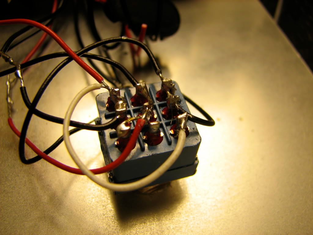
This is form the above linked thread, im not sure what is on the left of the image? Once I can get the other bit wired It seems I have to do whatever that is. Pointers?
Thanks!!
Last edited by cobascis on Mon Jan 03, 2011 4:00 am, edited 1 time in total.
Is it possible to just cut the wires going to the clip, strip like an inch back, then wrap it around another thicker piece of wire and heatshrink the join? Then solder the new wire to the switch.
I've never seen a wire "disintegrate" before so I have no idea what you mean by this. I'd imagine they are using super thin wire and perhaps the wire is just melting through, turn down the heat?
euan wrote:
I'm running in monoscope right now. I can't read multiple dimensions of meta right now
Pens wrote:Is it possible to just cut the wires going to the clip, strip like an inch back, then wrap it around another thicker piece of wire and heatshrink the join? Then solder the new wire to the switch.
I've never seen a wire "disintegrate" before so I have no idea what you mean by this. I'd imagine they are using super thin wire and perhaps the wire is just melting through, turn down the heat?
Disintegrate isn't really the right word - There are 3 incredibly thin strands, and the just break off if any pressure is applied.
You think if I can wrap em around a new wire it'd work. I think ill see how that goes.
If thats the case, then yeah I'd strip a long section of the thin wire, then strip about half inch of decent 22 gauge wire, wrap the thin around the new wire, solder+heatshrink and take it to your switch.
Best way would be to desolder the white clip from the board and run new wires to the pads, but that can be tricky sometimes. I'd try to work with the existing wire if possible.
euan wrote:
I'm running in monoscope right now. I can't read multiple dimensions of meta right now
Pens wrote:If thats the case, then yeah I'd strip a long section of the thin wire, then strip about half inch of decent 22 gauge wire, wrap the thin around the new wire, solder+heatshrink and take it to your switch.
Best way would be to desolder the white clip from the board and run new wires to the pads, but that can be tricky sometimes. I'd try to work with the existing wire if possible.
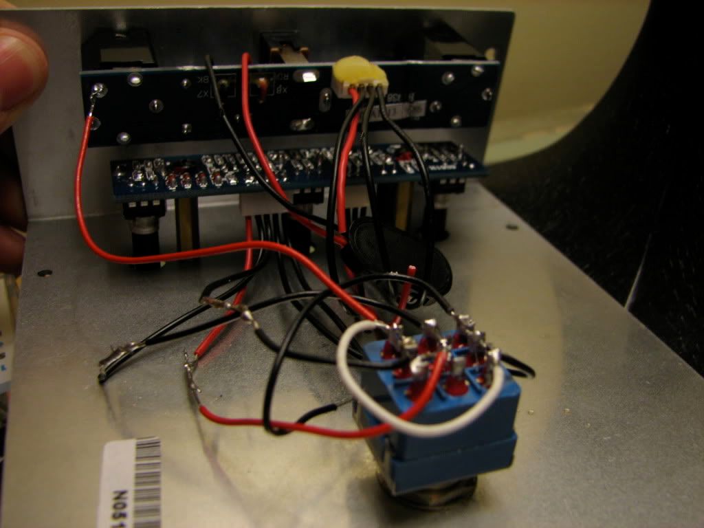
How/what do you heatshrink with? Also I wired it up and it doesn't turn on or pass a signal. I think it has to do with the thing on the left of the image, I just soldered a wire from that bit on the jack to the switch, why is the pictured one thick??
Honestly, I cannot debug this thing at all based on that image. I do not know the circuit, nor do I have it in front of me to trace the wires around to figure out what is what.
Switching a pedal from buffered flip-flop on to TB is very very specific to the pedal itself, each one is a tad different although the concept is the same for each of them.
euan wrote:
I'm running in monoscope right now. I can't read multiple dimensions of meta right now
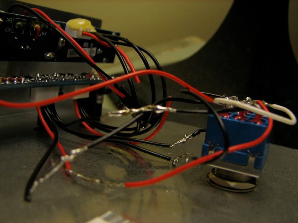
I realize how shoddy the connects are, how can I heat shrink wrap it? I'm just trying to figure out what is supposed to be soldered to what before I clean it up. And considering there is no power or sound getting to it, something is wrong..
Oh. Well it's too late to heat-shrink the joins. You have to put the tube on before you solder to the wire.
Basically, I meant you need to cover those joins where you made the little wire connect to the big wire so it doesn't short out. Just wrap some electrical tape around it now.
As to why it isn't working, again I can't debug what isn't in front of me. It's likely the wires aren't the same between the diagram you were using vs what is actually in that pedal.
euan wrote:
I'm running in monoscope right now. I can't read multiple dimensions of meta right now
So I can't really do much else. I don't know much about electronics; I just follow online shite. I thought this would've been easier than modding the MXR, I guess not.
The problem is you are using the true bypass instructions for the Phaser on your Behringer Muff. The wires just aren't going to be the same. I'd be amazed if they were! You need to wrap those wire junctions in something. If they hit the metal enclosure you will have a short.
The phaser schematic and true bypass instructions for the phaser are completely irrelevant. You need a schematic for your pedal. That's the first problem. Second, identify they type of switching that was originally used in the pedal and modify or bypass it to be always on. This switching may be the only thing in common with the phaser. Third, you need to identify the inputs and outputs of the actual muff circuit.
Bill Oakley wrote:The phaser schematic and true bypass instructions for the phaser are completely irrelevant. You need a schematic for your pedal. That's the first problem. Second, identify they type of switching that was originally used in the pedal and modify or bypass it to be always on. This switching may be the only thing in common with the phaser. Third, you need to identify the inputs and outputs of the actual muff circuit.
Well I haven't been able to source any schematics for the VD-1. Also, it was a springloaded switch that pressed a momentary switch on pcb
That means the real switching is done on the board. I'm not sure how Behringer switches theirs on.
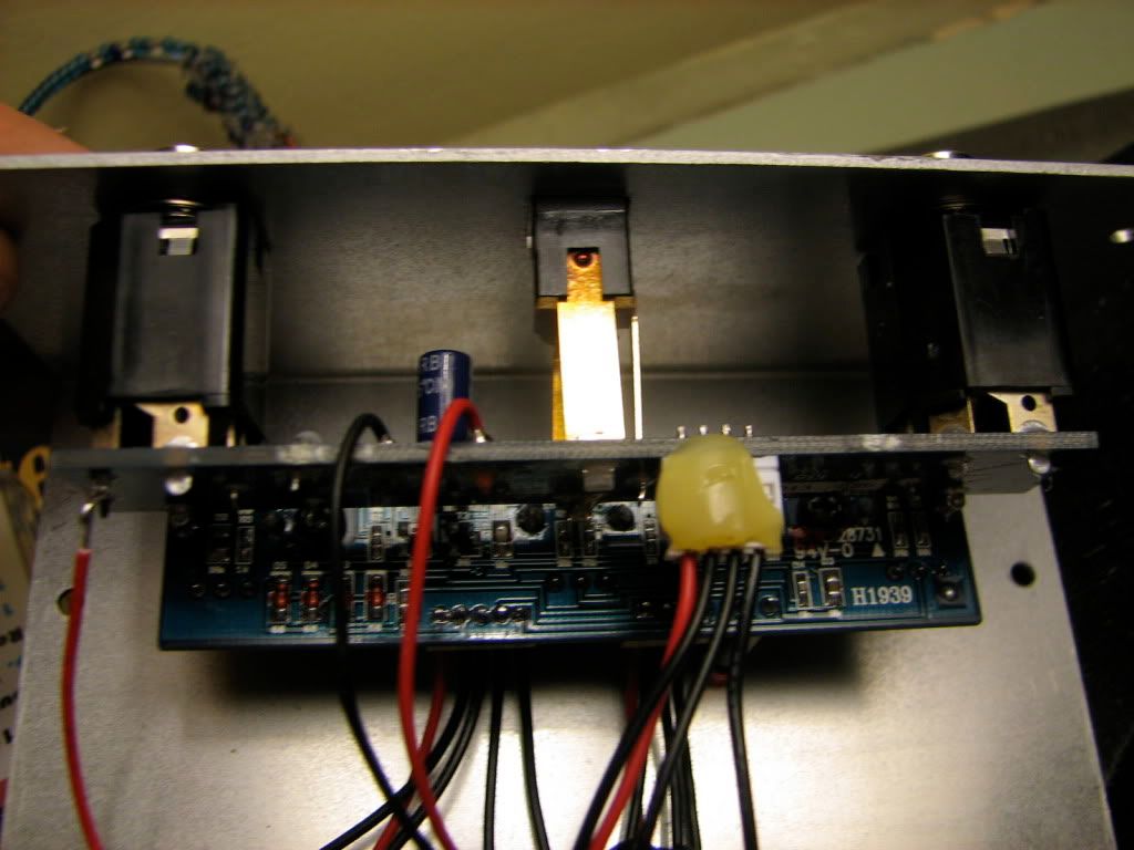
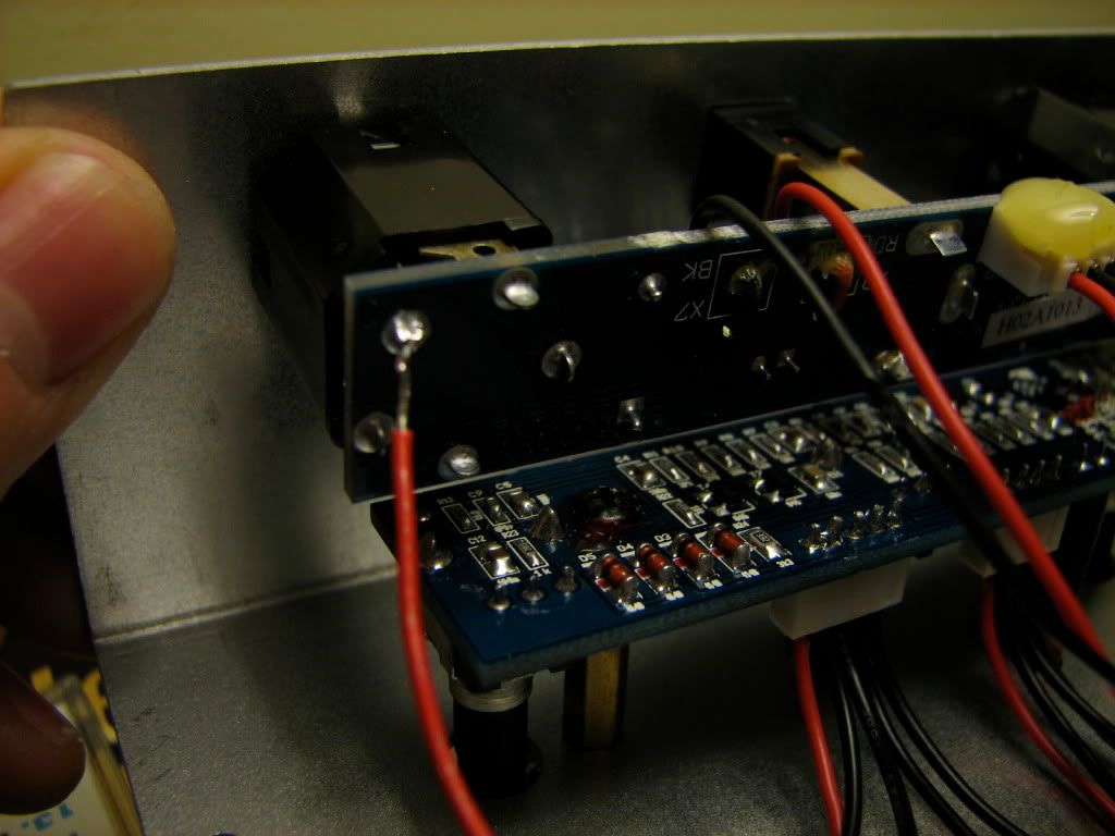
How about posting some really good pictures of both sides of the boards. Maybe we can make a schematic for it. That's going to help you out the most.
Have you tried contacting Behringer to see if they will give you the schematic? Just say you bought one used and most of the wires are off and you need a schematic to know where they go.
So I just attached the red wire on the left (that was previously clipped). Now, I have power. With that wire disconnected, there was only a bypass signal, no effected signal, no power, etc. Now with it connected there is power and only an effected signal. I need to find the middle ground, any ideas?
Can you post pics of the circuit board? Straight on and very clear so I can read the screen printing. A few of the trace side would be good also.
It'd be easier to help you out.
Kinda old thread, but I just wanted to point out that you missed the white wire that goes right to the "tip" leg of the input jack. That´s the one carrying the input signal and it´s shielded by the thick gray one. It´s hard to see in the first picture but it´s there, almost completely covered by the new red wire, which is actually the shield being grounded.
Last edited by davelectro on Tue Mar 23, 2010 4:17 am, edited 1 time in total.
No, that´s a shielded wire and its purpose is to reduce noise (a must in this case!). Right now you are not passing any signal from the input to the 3PDT switch. You need to use the "tip" lug to make the pedal work.