+1000!!!endsjustifymeans wrote:understatement.matt.dines wrote:man your such an asset to this site!
Veroboard Layouts for the hobbyist
Moderated By: mods
-
matt.dines

- .

- Posts: 250
- Joined: Thu Oct 22, 2009 2:37 pm
- Location: Birmingham
-
Mike

- I like EL34s
- Posts: 39170
- Joined: Thu Apr 20, 2006 8:30 am
- Location: Edinburgh, Scotland
- Contact:
Lest we forget FilterCap's crucial input to get it working on the Amp side though. He saved our bacon there!endsjustifymeans wrote:Works a charm. Love that pedal, really increased the versatility of my Mig.Mike wrote:Yeah the A/B was designed for Ends, I believe it has a Saltbooster on/off switch, an A OR B switch and an A AND B switch. Basically it's routing one signal, the input through an optional Saltbooster and then to either amp A, amp B or amp A and Amp B
-
endsjustifymeans

- Grown Up Punk
- Posts: 19442
- Joined: Tue Feb 10, 2009 4:02 pm
- Location: Ball So Hard University
That he did, I owe both you guys.Mike wrote:Lest we forget FilterCap's crucial input to get it working on the Amp side though. He saved our bacon there!endsjustifymeans wrote:Works a charm. Love that pedal, really increased the versatility of my Mig.Mike wrote:Yeah the A/B was designed for Ends, I believe it has a Saltbooster on/off switch, an A OR B switch and an A AND B switch. Basically it's routing one signal, the input through an optional Saltbooster and then to either amp A, amp B or amp A and Amp B
dots wrote:society is crumbling because of asshoels like ends
brainfur wrote:I'm having difficulty reconciling my desire to smash the state & kill all white people with my desire for a new telecaster
-
matt.dines
- .
- Posts: 250
- Joined: Thu Oct 22, 2009 2:37 pm
- Location: Birmingham
-
matt.dines
- .
- Posts: 250
- Joined: Thu Oct 22, 2009 2:37 pm
- Location: Birmingham
-
Mustang Melx
- .
- Posts: 323
- Joined: Wed Jul 02, 2008 4:15 pm
Re: Veroboard Layouts for the hobbyist
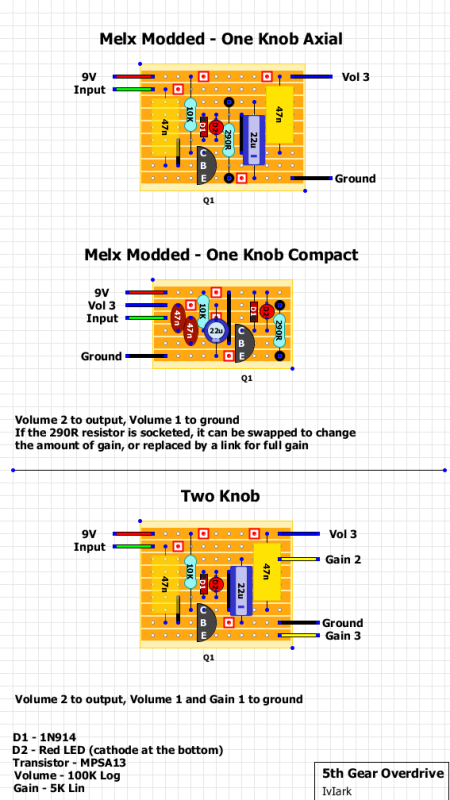
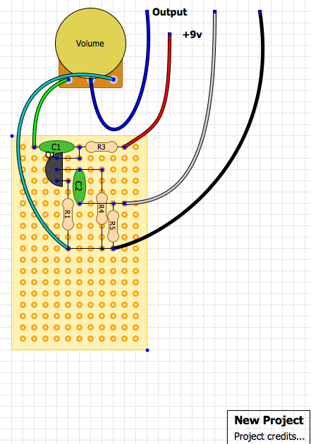
Hey Mike, I built this over the last couple of days and it took me ages to figure out why it wasn't working...Mike wrote:I figure these might be useful to some people here, I'll add them as I come across them and/or design them.
C1, the polarity should be the other way.
C3, needs to come down another row to 'F'
and I think the green wire should go to 'fuzz 1' not 'fuzz 3'
lol, that was a hell of a nightmare for a novice builder diy-er, but I leaned a lot from it!!
p.s. that 2N5088 bazz fuzz sounds fucking great!!


-
Mustang Melx
- .
- Posts: 323
- Joined: Wed Jul 02, 2008 4:15 pm
-
Mustang Melx
- .
- Posts: 323
- Joined: Wed Jul 02, 2008 4:15 pm

I was wondering how to read veroboard layouts (more put of curiosity than any ambition to build anything soon) and came across this site that has fair whack of information on it. I thought it was pertinent and decided to post it here:
http://www.zen22142.zen.co.uk/index.html
http://www.zen22142.zen.co.uk/index.html

-
SKC Willie

- Bunk Ass Fuck
- Posts: 3465
- Joined: Thu Nov 05, 2009 5:46 pm
- Location: Columbia, MO
- Contact:
Re: Veroboard Layouts for the hobbyist
Yes, I was wondering how to read these as well. Do you connect everything that is on row a together and then everything that is on the columns together? Or is it not that easy? And what is that red square with a dot in it?
twitter.com/skcwillie
follow me . . . . you won't
follow me . . . . you won't
-
SKC Willie
- Bunk Ass Fuck
- Posts: 3465
- Joined: Thu Nov 05, 2009 5:46 pm
- Location: Columbia, MO
- Contact:

veroboard is a special kind of printed circuit board with rows of holes connected together. so all the holes in each row are connected unless you cut the trace (as mike indicates here with the red squares).
more here: http://en.wikipedia.org/wiki/Stripboard
more here: http://en.wikipedia.org/wiki/Stripboard
-
24HRS2MDNT

- .
- Posts: 360
- Joined: Thu Jul 22, 2010 3:47 am
- Location: Ontario Canada