Oh. Ok. I use perf and strip mostly for prototyping or if I'm doing a little add-on circuit in say a Boss pedal. Etching is a little more involved.
When it comes time, I'll be glad to help if you need it.
Building Pedals
Moderated By: mods
-
Bill Oakley
- .

- Posts: 334
- Joined: Sat Sep 26, 2009 6:16 am
- Location: Kennewick, WA
- Contact:
-
SKC Willie

- Bunk Ass Fuck
- Posts: 3465
- Joined: Thu Nov 05, 2009 5:46 pm
- Location: Columbia, MO
- Contact:
Okay, I have a couple questions about the schematic you posted. First, I assume the difference between A and B pots are that one is linear and one is not. Which is A and B? What is the deal with the power coming into the pedal? And I need a parts list (and a picture of the inside of one of these would be nice), is there a place I could find that stuff?Bill Oakley wrote:Oh. Ok. I use perf and strip mostly for prototyping or if I'm doing a little add-on circuit in say a Boss pedal. Etching is a little more involved.
When it comes time, I'll be glad to help if you need it.
twitter.com/skcwillie
follow me . . . . you won't
follow me . . . . you won't
-
Bill Oakley
- .
- Posts: 334
- Joined: Sat Sep 26, 2009 6:16 am
- Location: Kennewick, WA
- Contact:
A=Log or audioportugalwillie wrote:Okay, I have a couple questions about the schematic you posted. First, I assume the difference between A and B pots are that one is linear and one is not. Which is A and B? What is the deal with the power coming into the pedal? And I need a parts list (and a picture of the inside of one of these would be nice), is there a place I could find that stuff?Bill Oakley wrote:Oh. Ok. I use perf and strip mostly for prototyping or if I'm doing a little add-on circuit in say a Boss pedal. Etching is a little more involved.
When it comes time, I'll be glad to help if you need it.
B= Linear
What about the power coming into the pedal? +9v connects where it says +9v. Is that what you're asking?
All the parts values and references are on the schematic. I'll make a BOM if you want though. There's not too many parts so it's pretty easy. Don't know if you'll find a picture of the inside of one. Don't know anyone who has built one and not sure how much it would help anyway. Why do you want a gut shot? To see a layout? Wiring? I'll make a layout if you need one or I'll help you make one.
-
SKC Willie
- Bunk Ass Fuck
- Posts: 3465
- Joined: Thu Nov 05, 2009 5:46 pm
- Location: Columbia, MO
- Contact:
-
matt.dines

- .
- Posts: 250
- Joined: Thu Oct 22, 2009 2:37 pm
- Location: Birmingham

You'll see that labeled Vb in some schematics. Its a voltage bias, in most cases 4.5v. You dont need to worry about values for now, just remember that every thing labeled 9v is connected together, everything labeled Vr go together and all the grounds go together.portugalwillie wrote:I was just curious to see how every fit together.
I see the +9 volts but what are the other little circles with a plus in them that are labeled vr?
No.
-
Bill Oakley
- .
- Posts: 334
- Joined: Sat Sep 26, 2009 6:16 am
- Location: Kennewick, WA
- Contact:
Exactly. I just chose vr as it was the first thing I "grabbed" in my schematics program. It's 1/2 voltage/bias voltage/4.5v whatever you want to call/label it!Shaguar wrote:You'll see that labeled Vb in some schematics. Its a voltage bias, in most cases 4.5v. You dont need to worry about values for now, just remember that every thing labeled 9v is connected together, everything labeled Vr go together and all the grounds go together.portugalwillie wrote:I was just curious to see how every fit together.
I see the +9 volts but what are the other little circles with a plus in them that are labeled vr?
"I was just curious to see how every fit together."
It's going to depend on the size of the board you use, size of enclosure and how you want the knobs, LED, and switch laid out.
First thing to do would be to get a layout done to see what size enclosure you can put it in. Using board mounted pots may save you a little wiring and room but may make the board a little bigger if you can't get a good layout. Plus board mounted pots on perf or stripboard are kind of hard/weird. I only do that when I etch a board.

Okay, I just got Der Molie kit this morning, and realised I hadn't really looked at the wiring diagram. So I did. I don't understand it. I did basic electronics in primary school about 17 years ago, and I seem to have somehow forgotten everything in the intervening period (HOW?! LOL).
http://diy.musikding.de/images/stories/ ... schalt.pdf
Basically, where the R6 and C4 stuff all conforms to the board, do I just solder the caps and bits and shit into the two holes? I know it sounds obvious, but I hadn't thought about it at all. I mean, you can't solder something the wrong way round, right? Bear in mind that while I love science (I CAN SEE THE MOON BUT IT IS ACTUALLY FAR AWAY LIKE REALLY FAR!) my mind sort of sees electricity as acting like water, and I can't help but see this circuit diagram as a complicated Nintendo DS pipe game.

Brandon W wrote:you elites.


-
Bill Oakley
- .
- Posts: 334
- Joined: Sat Sep 26, 2009 6:16 am
- Location: Kennewick, WA
- Contact:
Yes, you can put things in backwards and your pedal won't work. With your kit, you are dealing with electrolytics, a diode, an LED, and a transistor. All of them have to go a certain way.ekwatts wrote:Okay, I just got Der Molie kit this morning, and realised I hadn't really looked at the wiring diagram. So I did. I don't understand it. I did basic electronics in primary school about 17 years ago, and I seem to have somehow forgotten everything in the intervening period (HOW?! LOL).
http://diy.musikding.de/images/stories/ ... schalt.pdf
Basically, where the R6 and C4 stuff all conforms to the board, do I just solder the caps and bits and shit into the two holes? I know it sounds obvious, but I hadn't thought about it at all. I mean, you can't solder something the wrong way round, right? Bear in mind that while I love science (I CAN SEE THE MOON BUT IT IS ACTUALLY FAR AWAY LIKE REALLY FAR!) my mind sort of sees electricity as acting like water, and I can't help but see this circuit diagram as a complicated Nintendo DS pipe game.
First the diode. The diode in the kit should have a line on it. The line goes where the line is on the board. Towards the bottom in the picture.
The transistor should be pretty easy to see how it goes. The flat part goes towards the bottom of the board. The board has a picture of how it should go.
The electrolytic caps, C3, C5 and possibly C1 (they have it set up to use either so I don't know what came with your kit) will have a line down one side of the cap. That is your negative leg. The negative is marked on the board with a white fill on the edge of the circle. For C1, they put a + where the positive goes if it's electrolytic.
The LED should have a flat spot on the plastic lip. That is the negative and is the side of the LED with the line in the schematic.
-
Mike

- I like EL34s
- Posts: 39170
- Joined: Thu Apr 20, 2006 8:30 am
- Location: Edinburgh, Scotland
- Contact:
Bill has this all under control.
Can't stress how much you should take your time and practise soldering, it'll nip many issues in the bud if you can solder well. Look up some video tutorials on it.
MIKE'S TOP TIPS:
1. Get a half decent iron, the CSI one is mad good for the price.
2. Make sure you have a damp sponge to clean the tip every so often
3. Apply heat to the joint of the component lead and the pad you're soldering and then the solder to that join, never the solder to the iron itself, you'll burn off the solder and overheat the pad/component
4. Take your time
5. No I won't fix it if you fuck it up.
Srsly though, cheers everybody. I'm gonna drill the enclosure for the bypass box out tomorrow, practice a bit of soldering and see how I get on from there. I'll probably be attempting the Mole in about a week or so. Am excite. Loved the sound of the bass-boosters I've seen on the net.
Brandon W wrote:you elites.
Mike, you're like a prophet.
So I've drilled the holes for the jack sockets on the double bypass:
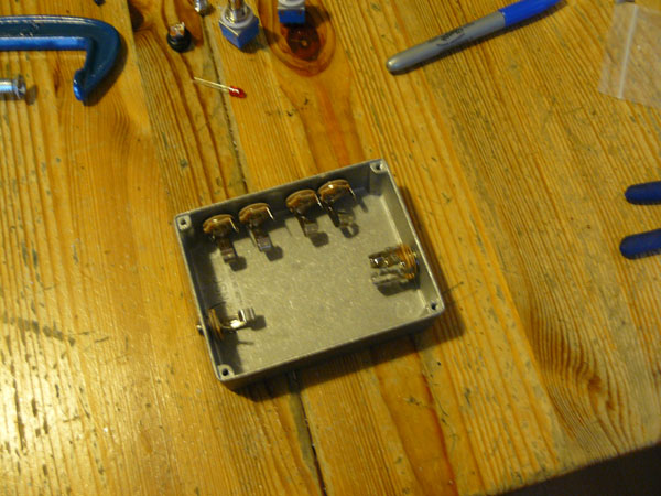
I'm worried that the two on the top right are way too close together. If they are turned, the curly bits that touch the jacks will touch, and potentially explode with a shower of dicks into my mouth.
The 12mm drill bit I got off eBay is also too wide to fit into my ghettofabulous 1973 electric drill, from a time when drills never needed to be larger than 9mm, so I'm going to have to look at one of those ones with a smaller shaft than the drill bit. I might take my first few tentative steps into soldering tonight.
It doesn't really help that this enclosure is really quite tiny. How do you pedal guys do it?
So I've drilled the holes for the jack sockets on the double bypass:
I'm worried that the two on the top right are way too close together. If they are turned, the curly bits that touch the jacks will touch, and potentially explode with a shower of dicks into my mouth.
The 12mm drill bit I got off eBay is also too wide to fit into my ghettofabulous 1973 electric drill, from a time when drills never needed to be larger than 9mm, so I'm going to have to look at one of those ones with a smaller shaft than the drill bit. I might take my first few tentative steps into soldering tonight.
It doesn't really help that this enclosure is really quite tiny. How do you pedal guys do it?
Brandon W wrote:you elites.
I'm just wondering where to jam the power socket, now, coz I didn't think about it before I started waving the drill around. I don't really want to stick it at the bottom because that means it takes up extra millimetres of pedalboard space I don't really have. I could put it next to one of the in/output jacks on the sides. I'll scope it out later when I sit down to do some soldering.
Brandon W wrote:you elites.
-
Bill Oakley
- .
- Posts: 334
- Joined: Sat Sep 26, 2009 6:16 am
- Location: Kennewick, WA
- Contact: