
Also, next time I drill some holes I'm going to use my little pin vise hand-drill to manually mark out some little dents, then drill the small guide holes into them, THEN drill the full size holes.
Also my drill has a switch on the top between 1 and 2. What's that all about? Is one of them a faster speed? I appeared to be drilling some odd triangular holes that I had widen a little.
Building Pedals
Moderated By: mods
-
Bill Oakley
- .

- Posts: 334
- Joined: Sat Sep 26, 2009 6:16 am
- Location: Kennewick, WA
- Contact:
Not sure what the numbers mean on your drill.
I used to punch little dents to use as a drill bit guide but I found it bent the enclosures a little. I now mark everything out in pencil and measure everything to make sure it's all lined up right. Then I drill small pilot holes, then go a little bigger so the end of my step drill bit fits in the hole, then drill it to full size with the step drill bit.
Nothing triggers my OCD more than jacks that aren't lined up! I would have filled the hole and drilled a new hole or just used a new enclosure. I couldn't stand looking down at that daily. That's just me though. I don't want to belittle your work. You are doing a good job and chose an excellent project to begin with.
Oh, these jack holes really are all over the fucking place. They look awful.
I drilled out all the guide holes using a 2mm drill. I'll definitely go with the small-to-big plan on the Molie, though.
I just bagged a reduced shaft 12mm drill on eBay. Soon as that comes I can jam the footswitches in as well.
Would youse guys recommend actually mounting all of the bits into their respective holes before soldering begins, or doing the soldering and then mounting the stuff afterwards?

Brandon W wrote:you elites.
-
Bill Oakley
- .
- Posts: 334
- Joined: Sat Sep 26, 2009 6:16 am
- Location: Kennewick, WA
- Contact:
Also, one last thing; I bought some 8mm DC jacks so I didn't have to buy a 13mm drill, but they only have two tags at the back instead of the three tags that the DC jacks supplied with the kits came with. Is this a problem? How does this change the layout, or would I be better to just buy a 13mm drill?
Brandon W wrote:you elites.
-
Bill Oakley
- .
- Posts: 334
- Joined: Sat Sep 26, 2009 6:16 am
- Location: Kennewick, WA
- Contact:
That'd be fine, I almost never use batteries for anything, everything is powered from a supply of some sort. Coolio.Bill Oakley wrote:The ones with 3 lugs are switching DC jacks. Meaning if you have a battery hooked up, it disconnects the battery and switches over to the AC power supply.
The 2 lug one will really only allow for either battery use OR an AC power supply. I don't think you could hook both up.
Brandon W wrote:you elites.
-
Mike

- I like EL34s
- Posts: 39170
- Joined: Thu Apr 20, 2006 8:30 am
- Location: Edinburgh, Scotland
- Contact:
They are isolated right? (i.e. plastic) because otherwise you might have goofed, some of the smaller jacks are metal and the outside will contact with the case when it's mounted, and since boss power is centre negative, and the outside of the jack will be positive, you don't want that.
Can you link to what you bought?
Can you link to what you bought?
This: http://www.musikding.de/product_info.ph ... mberg.html
It's plastic and says it's isolated like the other one, it's just that the mounting hole is smaller and it only has two tags. I didn't notice this when I bought it, though.
It's plastic and says it's isolated like the other one, it's just that the mounting hole is smaller and it only has two tags. I didn't notice this when I bought it, though.
Brandon W wrote:you elites.
-
Bill Oakley
- .
- Posts: 334
- Joined: Sat Sep 26, 2009 6:16 am
- Location: Kennewick, WA
- Contact:
Okay, while I wait for the 12mm drill to get to me, I'm doing a dry-fit of all the components of the Molie circuit board. Now, I think I have everything sort of where it should be, with all the transistors in the right way round and stuff.
Firstly, how can I tell which way round one of those little resistors is supposed to go? The banding on them really doesn't make it very clear. Secondly, what on earth is the 3-pin inline socket for? Where is it supposed to go? There are three sections of the circuitboard that have three holes each. But from the schematic, it would appear that those sections just accept transistors; one of them takes a 3-pin 2N transistor, while the other two appear to require a 3.3u transistor each.
The two 3.3u transistor sections are highlighted in red here:
Is the 3-pin inline socket even required? It's on the parts list, so it's not an extra or anything, and it doesn't feel quite right to leave any of the holes blank (but what do I know?*).
*evidently not very much.
Brandon W wrote:you elites.
-
Bill Oakley
- .
- Posts: 334
- Joined: Sat Sep 26, 2009 6:16 am
- Location: Kennewick, WA
- Contact:
Resistors aren't polarized so it doesn't matter which way they go in. Only the components I mentioned previously are polarized. The socket is for the transistor. If you apply too much heat to the transistor, you can burn it up. Put the socket in and then the transistor in the socket. This way you won't hurt it plus you can try different transistors without having to desolder and resolder.ekwatts wrote:Okay, while I wait for the 12mm drill to get to me, I'm doing a dry-fit of all the components of the Molie circuit board. Now, I think I have everything sort of where it should be, with all the transistors in the right way round and stuff.
Firstly, how can I tell which way round one of those little resistors is supposed to go? The banding on them really doesn't make it very clear. Secondly, what on earth is the 3-pin inline socket for? Where is it supposed to go? There are three sections of the circuitboard that have three holes each. But from the schematic, it would appear that those sections just accept transistors; one of them takes a 3-pin 2N transistor, while the other two appear to require a 3.3u transistor each.
The two 3.3u transistor sections are highlighted in red here:
Is the 3-pin inline socket even required? It's on the parts list, so it's not an extra or anything, and it doesn't feel quite right to leave any of the holes blank (but what do I know?*).
*evidently not very much.
Those 3.3u's are not transistors. They are capacitors. I explained how they go in a previous post. There are 3 holes for the 3.3u's because they made the board to accept different leg spacing. Put them in the holes that have the circle around them.
Ahh, excellent! That's a good idea. I'm most likely never going to change the transistor, but it's a good touch. Looks like I'm pretty much sorted now.
Now then, I'm going to do a bit of soldering practice later on one of jims old, shite guitars. If my drills arrive on Monday, I should be set up to just power through the bypass loop pedal and straight onto the Molie.
Now then, I'm going to do a bit of soldering practice later on one of jims old, shite guitars. If my drills arrive on Monday, I should be set up to just power through the bypass loop pedal and straight onto the Molie.
Brandon W wrote:you elites.
-
Bill Oakley
- .
- Posts: 334
- Joined: Sat Sep 26, 2009 6:16 am
- Location: Kennewick, WA
- Contact:
-
SKC Willie

- Bunk Ass Fuck
- Posts: 3465
- Joined: Thu Nov 05, 2009 5:46 pm
- Location: Columbia, MO
- Contact:
Okay. I've been learning about diodes, capacitors, and resistors. Most of what the Prof is talking about is over my head but no worries, I'm slowly catching on.
My soldering skills are pretty decent. They're not great but I've rewired several guitars (including Jags!) so I have a decent amount of practice, I'm just trying to figure out the best way to lay out all of my parts. Right now I'm getting a little stuck on the points that are not connected to anything. For example on the top circuit I see a capacitor followed by a resistor then the plus sign. Obviously resistors have two ends, so do I just leave one end not connected to anything? If that is that case, should I cut the end off so it doesn't come in contact with anything on accident? And all of the grounds, what should I be grounding them to?
I know these are super noob questions but I am one!
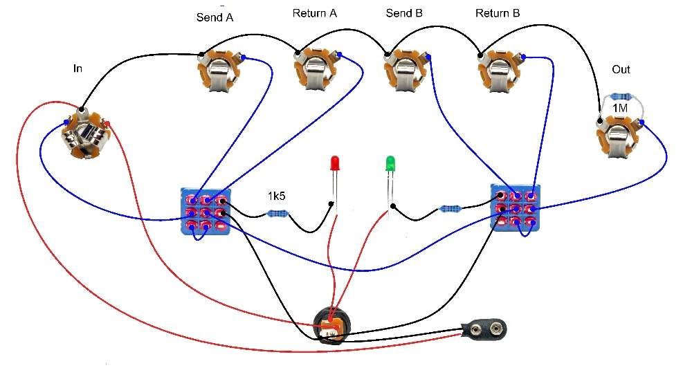
And just out of curiosity, the part of the circuit with the LED is only connected to the other parts of the circuit through the ground, I assume they all need to be grounded to the same place but does that part of the circuit actually effect the tone, or is all of that just for the LED?
My soldering skills are pretty decent. They're not great but I've rewired several guitars (including Jags!) so I have a decent amount of practice, I'm just trying to figure out the best way to lay out all of my parts. Right now I'm getting a little stuck on the points that are not connected to anything. For example on the top circuit I see a capacitor followed by a resistor then the plus sign. Obviously resistors have two ends, so do I just leave one end not connected to anything? If that is that case, should I cut the end off so it doesn't come in contact with anything on accident? And all of the grounds, what should I be grounding them to?
I know these are super noob questions but I am one!
And just out of curiosity, the part of the circuit with the LED is only connected to the other parts of the circuit through the ground, I assume they all need to be grounded to the same place but does that part of the circuit actually effect the tone, or is all of that just for the LED?
twitter.com/skcwillie
follow me . . . . you won't
follow me . . . . you won't