
See the VR by C11? All points marked VR connect to there. So the ends of R3 and R4 would connect to the positive side of C11.portugalwillie wrote:Okay. I've been learning about diodes, capacitors, and resistors. Most of what the Prof is talking about is over my head but no worries, I'm slowly catching on.
My soldering skills are pretty decent. They're not great but I've rewired several guitars (including Jags!) so I have a decent amount of practice, I'm just trying to figure out the best way to lay out all of my parts. Right now I'm getting a little stuck on the points that are not connected to anything. For example on the top circuit I see a capacitor followed by a resistor then the plus sign. Obviously resistors have two ends, so do I just leave one end not connected to anything? If that is that case, should I cut the end off so it doesn't come in contact with anything on accident? And all of the grounds, what should I be grounding them to?
I know these are super noob questions but I am one!
And just out of curiosity, the part of the circuit with the LED is only connected to the other parts of the circuit through the ground, I assume they all need to be grounded to the same place but does that part of the circuit actually effect the tone, or is all of that just for the LED?
Same exact thing with all the grounds. They all have to connect together.
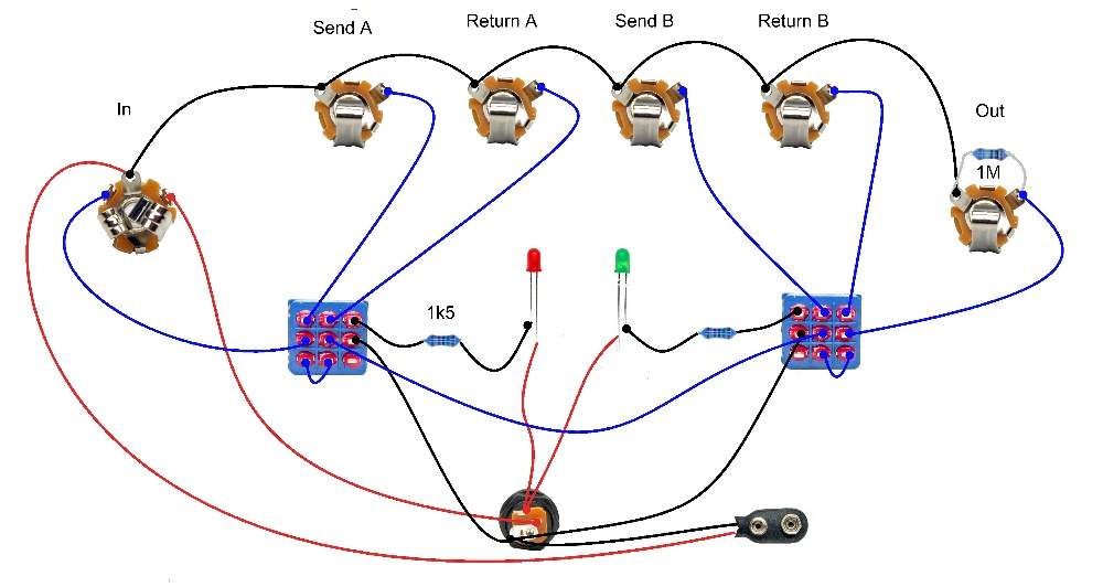
For the LED, you need to look online for true bypass switching diagrams. R16 is the Drop Down Resistor which controls how bright your LED is and the LED pad would connect to the positive leg of the LED. The other leg of the LED would connect to the switch. Hence looking online for bypass switching diagrams.


