Modded Behringer Big Muff DEMO
Moderated By: mods
-
davelectro
- .

- Posts: 6
- Joined: Tue Mar 23, 2010 12:13 am
-
davelectro
- .
- Posts: 6
- Joined: Tue Mar 23, 2010 12:13 am


-
davelectro
- .
- Posts: 6
- Joined: Tue Mar 23, 2010 12:13 am


-
davelectro
- .
- Posts: 6
- Joined: Tue Mar 23, 2010 12:13 am
-
Bill Oakley
- .
- Posts: 334
- Joined: Sat Sep 26, 2009 6:16 am
- Location: Kennewick, WA
- Contact:
-
Bill Oakley
- .
- Posts: 334
- Joined: Sat Sep 26, 2009 6:16 am
- Location: Kennewick, WA
- Contact:
Well, just messed around a bit more. That is only when I connect a wire that had to be cut. (See my other thread about the noise machine this turns into now when I connect the same wire).Bill Oakley wrote:Sounds like you wired the switch wrong.
As I have it now, bypass signal works fine, no effect. I followed the lines on the PCB and thought I have the the stuff matched up.
Been doing it to this:

-
Bill Oakley
- .
- Posts: 334
- Joined: Sat Sep 26, 2009 6:16 am
- Location: Kennewick, WA
- Contact:
That wiring should work fine. The problem has to be at the other end of the wires.
How did you make the effect stay always on?
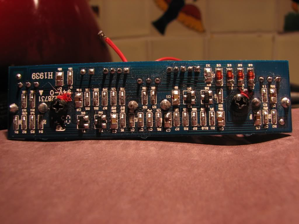
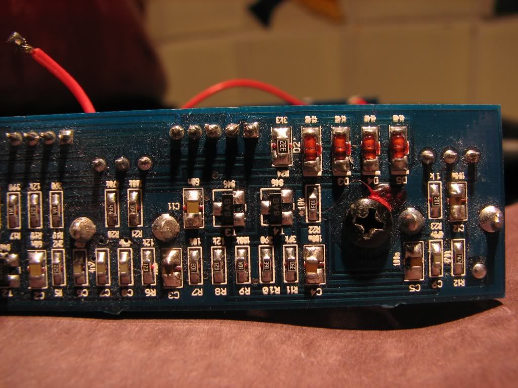
You know if you can take me some really good, big, and clear pictures of each side of each board as straight on as you can, I will look over it and make a schematic for it and we can see what's going on and lay this turkey to rest! I'll need to be able to read the resistor codes so use the macro setting on your camera if it has one, no flash but in plenty of light.
How did you make the effect stay always on?
You know if you can take me some really good, big, and clear pictures of each side of each board as straight on as you can, I will look over it and make a schematic for it and we can see what's going on and lay this turkey to rest! I'll need to be able to read the resistor codes so use the macro setting on your camera if it has one, no flash but in plenty of light.
When I connect those two red wires, the oscillation starts and the led and effect turn on. When I hit the switch it cuts out everything.Bill Oakley wrote:That wiring should work fine. The problem has to be at the other end of the wires.
How did you make the effect stay always on?
You know if you can take me some really good, big, and clear pictures of each side of each board as straight on as you can, I will look over it and make a schematic for it and we can see what's going on and lay this turkey to rest! I'll need to be able to read the resistor codes so use the macro setting on your camera if it has one, no flash but in plenty of light.
When those two red wires are NOT connected, just the bypass signal comes through.
I will try to take the pics for you, it is pretty hard to do with it all wired up.
-
Bill Oakley
- .
- Posts: 334
- Joined: Sat Sep 26, 2009 6:16 am
- Location: Kennewick, WA
- Contact:
I think it was a momentary (springloaded thing tha pushed a switch on a little PCB)
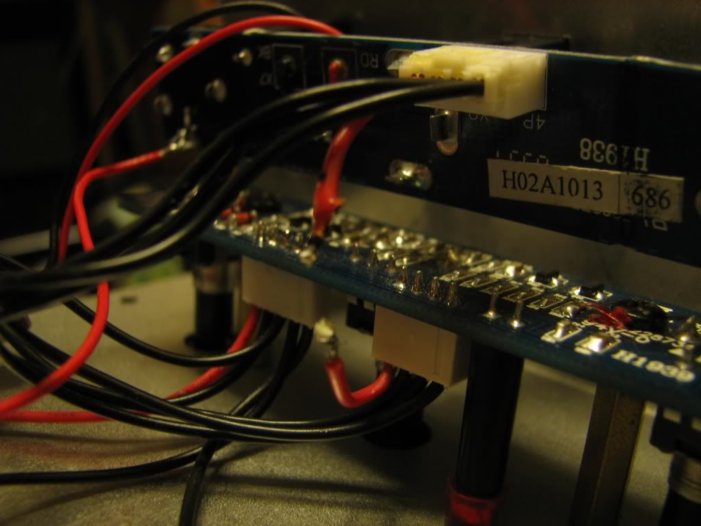
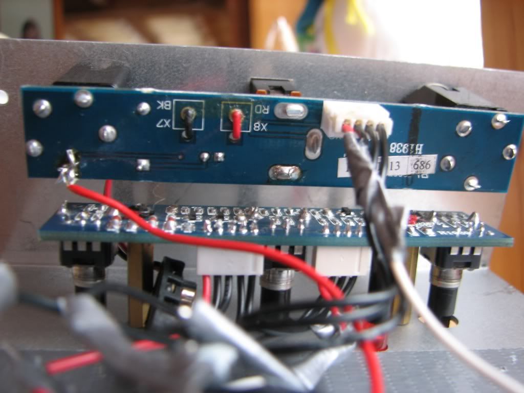
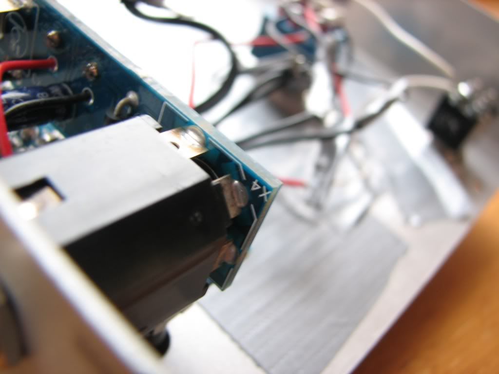
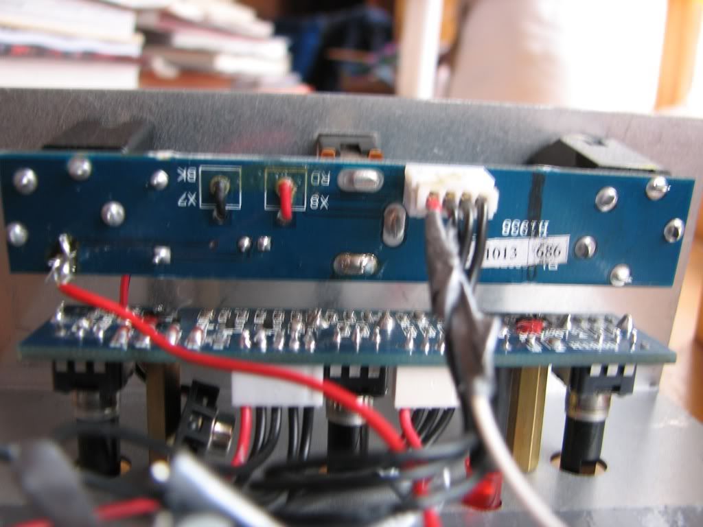
Do these work for you?
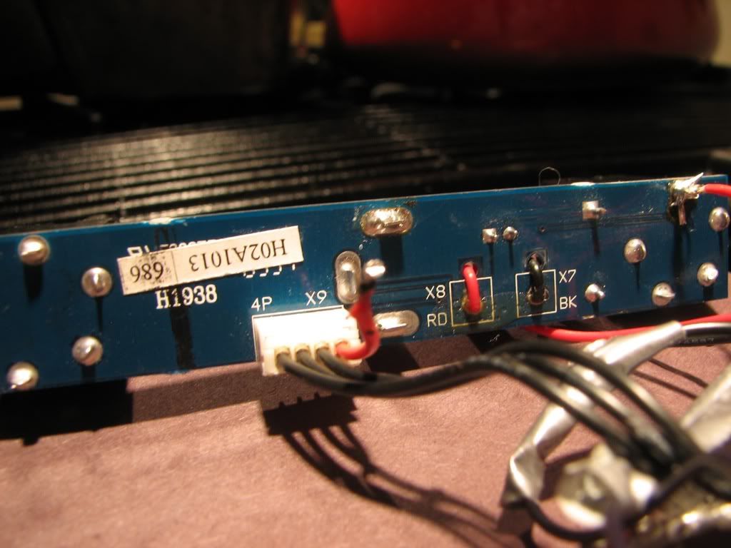
They are probably higher res here:
http://s261.photobucket.com/albums/ii46/linck-3/
Do these work for you?
They are probably higher res here:
http://s261.photobucket.com/albums/ii46/linck-3/
-
Bill Oakley
- .
- Posts: 334
- Joined: Sat Sep 26, 2009 6:16 am
- Location: Kennewick, WA
- Contact:
-
Bill Oakley
- .
- Posts: 334
- Joined: Sat Sep 26, 2009 6:16 am
- Location: Kennewick, WA
- Contact:
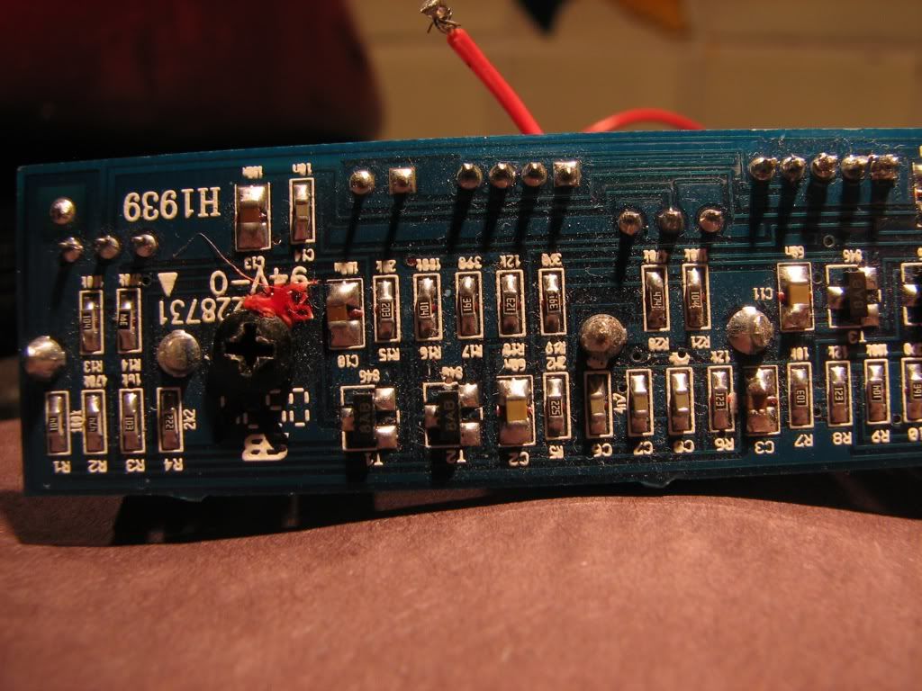
Worked on it for a little and have most of it traced out. I don't see any CMOS switching or anything so the original switch had to be a latching SPDT at the very least but if it's like the Phaser, it had a DPDT.
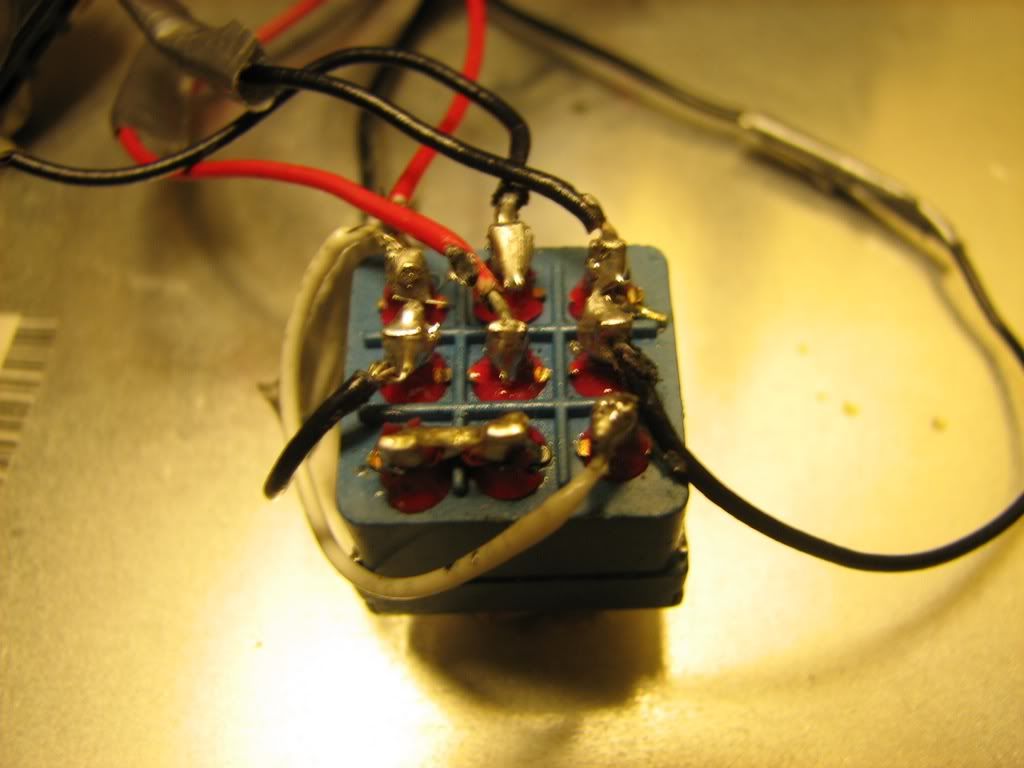
Before I forget, did you hook up that red wire to the lug of the input jack or was it like that? Could I get more pictures of the input and output jack board?
So from what I can tell from the pictures, the red wire on the right side of X1 leads to the FX input (R11/39K), the one next to it goes to the LED and R24/3K3, Not sure what the middle one goes to yet, the one second from the left connects to the far left on X2 and not sure where that goes yet, and the far left on on X1 is the FX output which comes of lug 2 of the Volume pot.
Not sure of many of the connections on X2 yet. I'm guessing they go to the Input/Ouput jack board.
I'll work on it a little more tomorrow.
Bill Oakley wrote:Worked on it for a little and have most of it traced out. I don't see any CMOS switching or anything so the original switch had to be a latching SPDT at the very least but if it's like the Phaser, it had a DPDT.
Before I forget, did you hook up that red wire to the lug of the input jack or was it like that? Could I get more pictures of the input and output jack board?
So from what I can tell from the pictures, the red wire on the right side of X1 leads to the FX input (R11/39K), the one next to it goes to the LED and R24/3K3, Not sure what the middle one goes to yet, the one second from the left connects to the far left on X2 and not sure where that goes yet, and the far left on on X1 is the FX output which comes of lug 2 of the Volume pot.
Not sure of many of the connections on X2 yet. I'm guessing they go to the Input/Ouput jack board.
I'll work on it a little more tomorrow.
The red wire was not there before (going to the input jack).
-
Bill Oakley
- .
- Posts: 334
- Joined: Sat Sep 26, 2009 6:16 am
- Location: Kennewick, WA
- Contact:
Ok. I don't know if I can go any further because all the traces I need to see are under components and jacks so you're going to have to do a little work here and I'll try to guide you through it.
Remove any wires you added. I think all the wires we need come right from the wire harnesses.
What connections we need: IN Jack, Out Jack, FX In, FX Out, Gnd, and 9v.
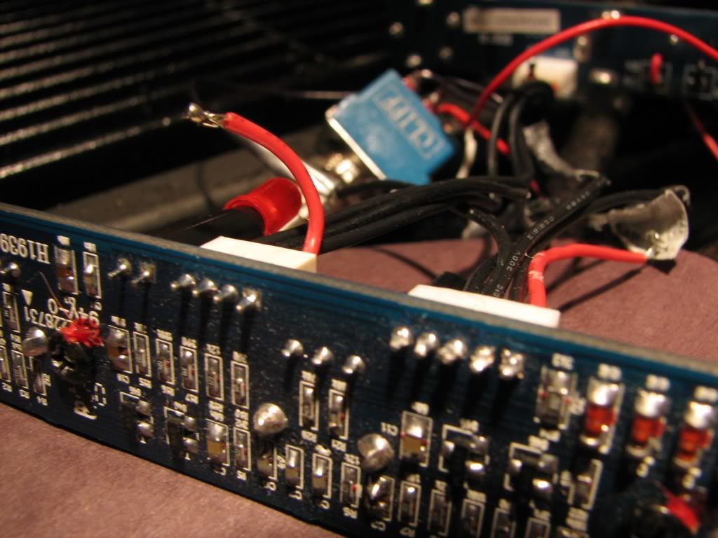
Let's start with X1. Looking at the harness we have 1 2 3 4 5
Wire 1 is the FX output wire from what I can gather. It connects to lug 2 of the volume pot.
Wire 5 (red) is the FX input. Connects to R11/39K.
Wire 4 connects to the LED and it's DDR R24/3K3
Wire 3 I can't tell where it goes
Wire 2 connects to connector X2 and we may have to sever this connection but don't do it yet. I can't really tell what it's for using the pictures yet.
So we have FX out, FX in, and the LED connection we are going to use on X1.
Now to X2. Looking at the harness we have 1 2 3 4
This is where I can't really tell what is what.
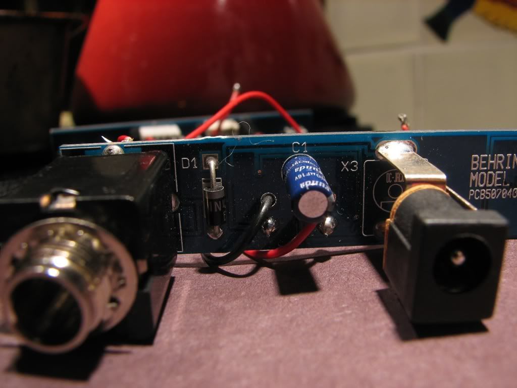
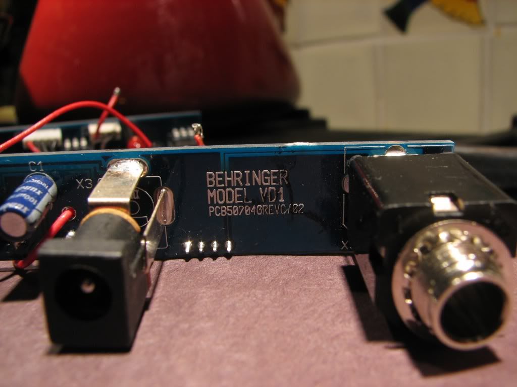
The 4 wires on this harness are going to be 9v, In jack tip, Out jack tip, and ground.
Start with 9v. Follow where the red battery wire goes. It should go to the DC jack. On the DC jack there are two other connections. One is ground and connects to the negative/black battery wire and the other is the 9v we are looking for. Follow this 9v to the harness. It should go to the + side of C1, the side of the diode D1 with the line on it and then go to the harness. This will be your 9v connection. Don't sever this. It needs to stay intact.
Do the same thing with the negative/black battery wire. Follow it from the wire to the harness. This would be ground.
Really neither of these are really that important at this point. It's just good to know where they are.
Input jack tip - Figure out what lug is the input jack tip connection. I can't tell from the pictures. They use 5 lug switching jacks that I never use so I'm not familiar with them. I can tell you the corner of the jack that has that 45 degree flat spot is the ground lug. This may be tough as you have to find the actual tip connection and not the switching one. Once you find it follow the traces back to the harness. This wire will be your In jack wire.
Do the same thing for the output jack.
You should have all the connections you need to wire up the switch now.
I'll need to look into the connection between X1 wire 2 and X2 wire 1. I don't know where the other end of these wires go to from the harness.
Remove any wires you added. I think all the wires we need come right from the wire harnesses.
What connections we need: IN Jack, Out Jack, FX In, FX Out, Gnd, and 9v.
Let's start with X1. Looking at the harness we have 1 2 3 4 5
Wire 1 is the FX output wire from what I can gather. It connects to lug 2 of the volume pot.
Wire 5 (red) is the FX input. Connects to R11/39K.
Wire 4 connects to the LED and it's DDR R24/3K3
Wire 3 I can't tell where it goes
Wire 2 connects to connector X2 and we may have to sever this connection but don't do it yet. I can't really tell what it's for using the pictures yet.
So we have FX out, FX in, and the LED connection we are going to use on X1.
Now to X2. Looking at the harness we have 1 2 3 4
This is where I can't really tell what is what.
The 4 wires on this harness are going to be 9v, In jack tip, Out jack tip, and ground.
Start with 9v. Follow where the red battery wire goes. It should go to the DC jack. On the DC jack there are two other connections. One is ground and connects to the negative/black battery wire and the other is the 9v we are looking for. Follow this 9v to the harness. It should go to the + side of C1, the side of the diode D1 with the line on it and then go to the harness. This will be your 9v connection. Don't sever this. It needs to stay intact.
Do the same thing with the negative/black battery wire. Follow it from the wire to the harness. This would be ground.
Really neither of these are really that important at this point. It's just good to know where they are.
Input jack tip - Figure out what lug is the input jack tip connection. I can't tell from the pictures. They use 5 lug switching jacks that I never use so I'm not familiar with them. I can tell you the corner of the jack that has that 45 degree flat spot is the ground lug. This may be tough as you have to find the actual tip connection and not the switching one. Once you find it follow the traces back to the harness. This wire will be your In jack wire.
Do the same thing for the output jack.
You should have all the connections you need to wire up the switch now.
I'll need to look into the connection between X1 wire 2 and X2 wire 1. I don't know where the other end of these wires go to from the harness.