Pickups, pedals, amps, cabs, combos
Moderated By: mods
cobascis
.
Posts: 3831 Joined: Sat Jun 21, 2008 4:31 pm
Post
by cobascis Sun Jan 02, 2011 10:41 pm
I just got it working!Now I just want to add the feedback loop that I accidentally made earlier.
cobascis
.
Posts: 3831 Joined: Sat Jun 21, 2008 4:31 pm
Post
by cobascis Mon Jan 03, 2011 4:00 am
[youtube]VIDEO
Blue Cool
.
Posts: 94 Joined: Mon Dec 13, 2010 10:44 pmLocation: Illinois
Post
by Blue Cool Mon Jan 03, 2011 4:05 am
Sounds good. Cool to see you got it working.
Bill Oakley
.
Posts: 334 Joined: Sat Sep 26, 2009 6:16 amLocation: Kennewick, WA
Contact:
Post
by Bill Oakley Mon Jan 03, 2011 4:09 am
cobascis wrote: I just got it working!Now I just want to add the feedback loop that I accidentally made earlier.
Glad to help.
Now you need to post a detailed illustration of what you did so other people can do it!
Bill Oakley
.
Posts: 334 Joined: Sat Sep 26, 2009 6:16 amLocation: Kennewick, WA
Contact:
Post
by Bill Oakley Mon Jan 03, 2011 4:35 am
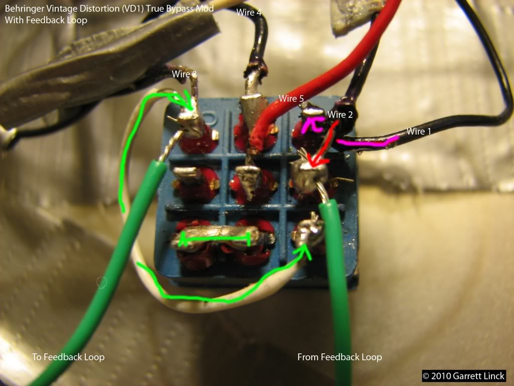
Is this what worked for you? Can you tell me which wires on X2 you used and what they were so I can finish the illustration?
cobascis
.
Posts: 3831 Joined: Sat Jun 21, 2008 4:31 pm
Post
by cobascis Mon Jan 03, 2011 12:41 pm
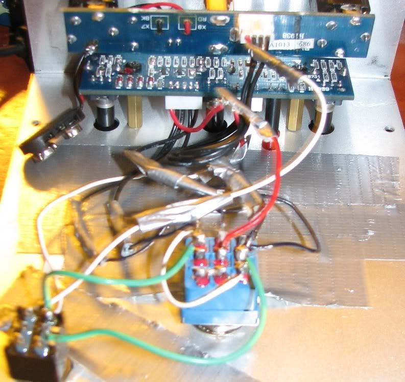
I'll take a better picture after school.
You can see nothing is soldered to the middle left post, interesting.
Berto
.
Posts: 358 Joined: Sun Dec 06, 2009 6:39 pmLocation: Vermont
Post
by Berto Mon Jan 03, 2011 9:32 pm
can you draw out the connections to the switch posts and where the leads go?
IroniaSudby wrote: I just 4chan'd a little.
hotrodperlmutter
crescent fresh
Posts: 16665 Joined: Sat Apr 04, 2009 10:29 pmLocation: Overland Park, KS, USA
Post
by hotrodperlmutter Mon Jan 03, 2011 9:39 pm
that thing sounds fucking awesome dude. much better than when i had it.
dots wrote: fuck that guy in his bunkhole.
proroby
.
Posts: 65 Joined: Wed Nov 03, 2010 8:28 pm
Post
by proroby Mon Jan 03, 2011 10:23 pm
Thats a killer muFF
There's a snake in my boots. Someone poisoned the water hole!
cobascis
.
Posts: 3831 Joined: Sat Jun 21, 2008 4:31 pm
Post
by cobascis Mon Jan 03, 2011 10:25 pm
All you need to edit your mock-up should be there I think.
cobascis
.
Posts: 3831 Joined: Sat Jun 21, 2008 4:31 pm
Post
by cobascis Tue Jan 04, 2011 12:10 am
Hey, after using the muff at volume with the amp I realized the feedback bit is comparitvely quiet. What sort of bits would I have to add in order to boost this volume?
hotrodperlmutter
crescent fresh
Posts: 16665 Joined: Sat Apr 04, 2009 10:29 pmLocation: Overland Park, KS, USA
Post
by hotrodperlmutter Tue Jan 04, 2011 1:16 am
You probably most definitley need to wire your clear water thunder through it and just see if that helps.
dots wrote: fuck that guy in his bunkhole.
cobascis
.
Posts: 3831 Joined: Sat Jun 21, 2008 4:31 pm
Post
by cobascis Tue Jan 04, 2011 1:26 am
hotrodperlmutter wrote: You probably most definitley need to wire your clear water thunder through it and just see if that helps.
weirdly, I was just stalking aen on the ilovefuzz forums, and he based the ECT on the behringer version of the muff!
ha, I should add a tone bypass mod, and it will be a behringer ECT