

Fender Starcaster Chorus letdown
Moderated By: mods
-
endsjustifymeans

- Grown Up Punk
- Posts: 19442
- Joined: Tue Feb 10, 2009 4:02 pm
- Location: Ball So Hard University
Dave's has had some personal touches added by yours truly. It's cooler than decpeticons, which is a hard thing to do.
dots wrote:society is crumbling because of asshoels like ends
brainfur wrote:I'm having difficulty reconciling my desire to smash the state & kill all white people with my desire for a new telecaster


mine arrived today and I had a quick tinker and it seems pretty cool. Its definitely a hefty pedal though. I just need some extra time to sit down with all my new arrivals and spend some serious time getting to know them intimately
plopswagon wrote:I like teles and strats because they're made out of guitar.
robroe wrote:I dont need a capo. I have the other chords in my tonefingers
-
Bill Oakley
- .

- Posts: 334
- Joined: Sat Sep 26, 2009 6:16 am
- Location: Kennewick, WA
- Contact:
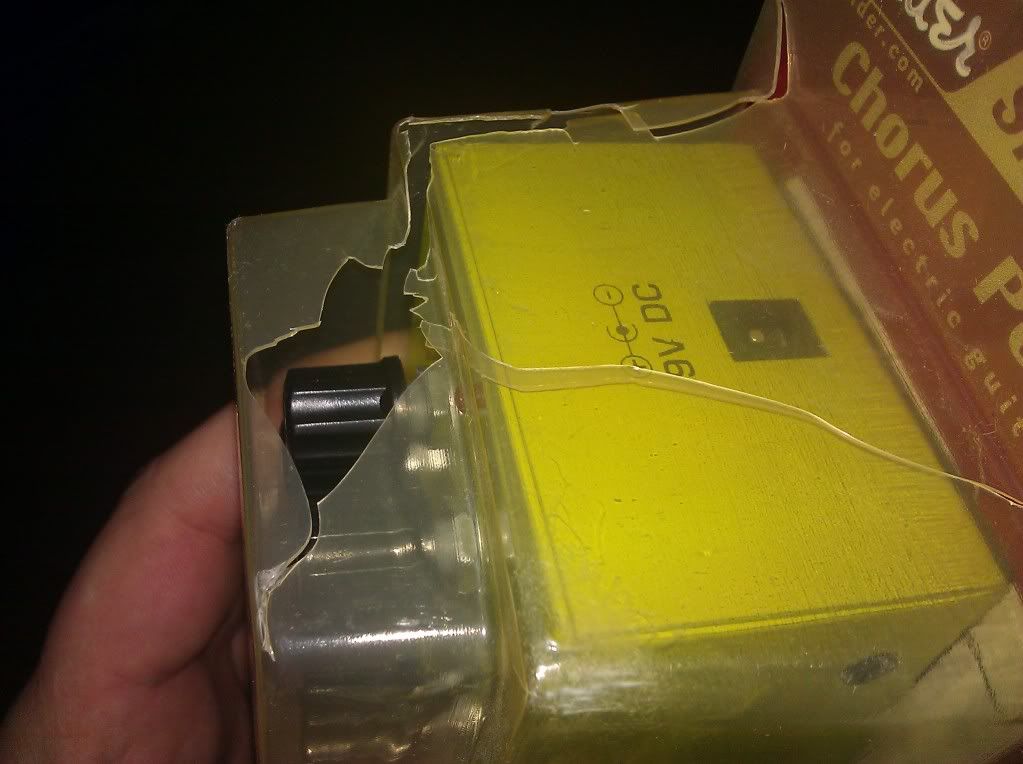
I got mine today. The packing was horrible. It was bouncing around in the box. It was put in a big box with a small piece of brown paper that didn't do much. The plastic packaging was busted up all over. Made it easy to get out though. Luckily nothing was broken. Pedal works fine and sounds pretty good. Very good for $10. Well, after playing it for a few minutes, I had to open it up. First thing I thought of was it's a non-stereo Boss CE-5 clone. At first glance of the insides, I think I'm right. I'll have to take a better look at it and compare it to the CE-5 schematic when I get some time. I don't think it's true bypass either. I'll have to look at that better also.
Maybe when I get a better look at it and since these pedals are so cheap, I'll post a few mods for it. Maybe true bypass, possibly making it stereo like the CE-5, blinking Rate LED, and maybe a few things to make it crazy for the people that like noisy things. Probably can do vibrato with it also.
Maybe when I get a better look at it and since these pedals are so cheap, I'll post a few mods for it. Maybe true bypass, possibly making it stereo like the CE-5, blinking Rate LED, and maybe a few things to make it crazy for the people that like noisy things. Probably can do vibrato with it also.
-
taylornutt

- .

- Posts: 4908
- Joined: Thu Sep 17, 2009 5:04 pm
- Location: Dallas, TX
-
Bill Oakley
- .
- Posts: 334
- Joined: Sat Sep 26, 2009 6:16 am
- Location: Kennewick, WA
- Contact:
Well, I didn't look too well at it but it looked like two wires hooked up to the input jack which led me to believe they were just switching inputs or maybe it was the output jack. I'll have to look again. They are using a DPDT and one lug isn't used and there is an LED status indicator. That also made me believe it wasn't true bypass. I'll look again.
EDIT: Well I was bored tonight and I sat down and went through this whole thing. It is a Boss CE-5 exactly. Well, without the FET switching and the stereo output. I went through each component and verified the values. I even marked the CE-5 schematic with the Fender's references. I'll clean it up and post it when I'm done. The only thing that was a little different was the power section, one resistor value (R43 is 33k instead of 39k as in the CE-5), and the BBD chips are MN3101/MN3007 in the CE-5 and they are 3102/3207 in the Fender.
This thing is definitely NOT true bypass. The FX input AND the switch are both connected to the tip of the input jack which means the input is connected all the time. The switch uses two other lugs. One to the output tip and one to the FX output. The two other lugs on the other side of the switch just switch the LED on/off.
-
Bill Oakley
- .
- Posts: 334
- Joined: Sat Sep 26, 2009 6:16 am
- Location: Kennewick, WA
- Contact:
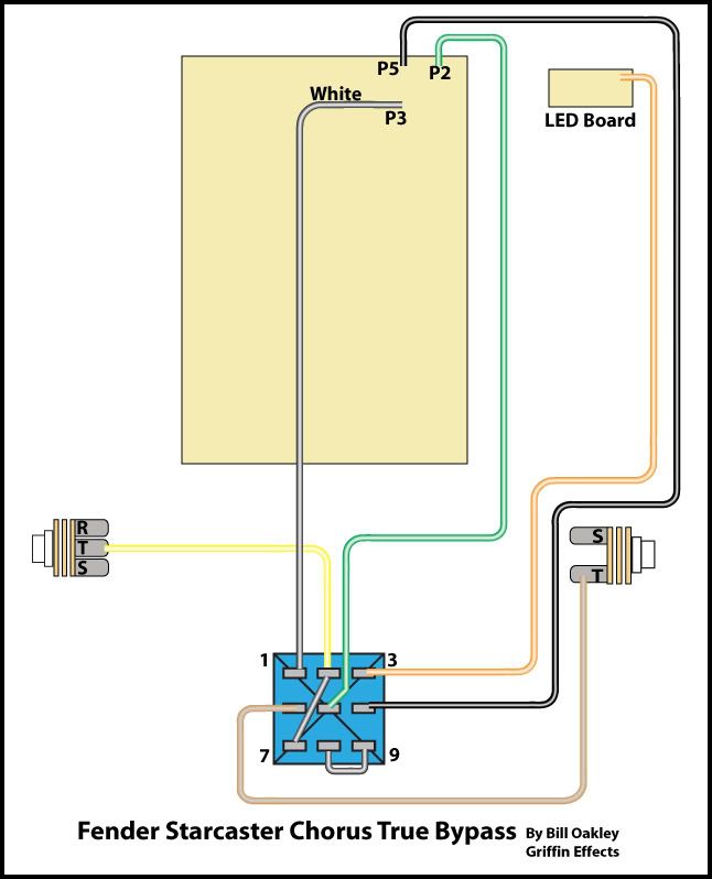
Here's the first mod for the Fender Starcaster Chorus: True Bypass with LED.
The only part you will need is a 3pdt switch. You could do millenium bypass with the stock switch if you wanted to but I won't go into that.
1. Remove any power supply/battery.
2. Remove all the wires from the switch and remove the switch.
3. Replace the switch with a 3pdt switch.
4. Solder a jumper between lugs 8 and 9 of the switch.
5. Take the white wire that was on the old switch and solder it to lug 1 of the new switch.
6. Take the yellow wire that was on the old switch and solder it to lug 2 of the new switch. Solder a jumper from lug 2 to lug 7 of the switch.
7. Take the orange wire that was on the old switch and solder it to lug 3 of the new switch.
8. Take the brown wire that was on the old switch and solder it to lug 4 of the new switch.
9. Remove the green wire from the input jack tip. Solder it to lug 5 of the new switch.
10. Take the black wire that was on the old switch and solder it to lug 6 of the new switch.
It's now true bypass.

+11 I think I could handle that. If you get more please do post! I plan to keep hold of mine as i doubt I'll ever need some whizzy super chorus for big bucks and mine will have Ends lovejooz all over it. Any chance to add bits to it sounds like fun to melorez wrote:thanks for that Bill, it would be interesting to see what others you figure out from your list. I'm sure I'll give at least this one a go
iCEByTes wrote:5 Most Jizz face maker Solo�s , classic Rock music i ever listened.
iCEByTes wrote:Blunt a joint , Take the Touch , Listen this.
-
endsjustifymeans
- Grown Up Punk
- Posts: 19442
- Joined: Tue Feb 10, 2009 4:02 pm
- Location: Ball So Hard University
endsjustifymeans wrote:the potent kindlorez wrote:what lovejooz did ends add?

Nerd fact: From my gamesworkshop teen years I can tell the makers of Alien just built that effect from polystyrene and poured polystyrene cement glue on it.
iCEByTes wrote:5 Most Jizz face maker Solo�s , classic Rock music i ever listened.
iCEByTes wrote:Blunt a joint , Take the Touch , Listen this.
-
Bill Oakley
- .
- Posts: 334
- Joined: Sat Sep 26, 2009 6:16 am
- Location: Kennewick, WA
- Contact:
mmmpls! As someone who doesn't know shit about schematics it's your list that I can really follow - "stick that there, NO DON'T STICK IT THER! oh yeah, right there - that's it". Can follow that!Bill Oakley wrote:I'll get some more mods up for it in a little bit. I need to get some time to do the illustrations.
I'll do vibrato and blinking LED next.
iCEByTes wrote:5 Most Jizz face maker Solo�s , classic Rock music i ever listened.
iCEByTes wrote:Blunt a joint , Take the Touch , Listen this.
-
endsjustifymeans
- Grown Up Punk
- Posts: 19442
- Joined: Tue Feb 10, 2009 4:02 pm
- Location: Ball So Hard University
-
Bill Oakley
- .
- Posts: 334
- Joined: Sat Sep 26, 2009 6:16 am
- Location: Kennewick, WA
- Contact:
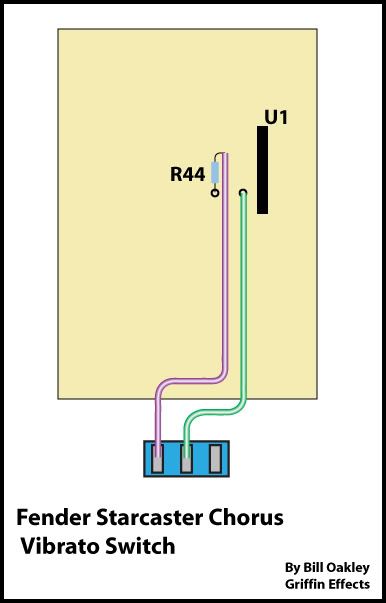
Ok. Here is the vibrato mod:
What you will need:
Spst switch (I know the illustration shows an Spdt)
Wire
1. Lift the leg of R44.
2. Solder a piece of wire to the lifted leg. Solder the other end of this wire to the outside lug of the switch. Make sure the wires are long enough to reach where you want to put the switch.
3. Solder a piece of wire to the empty R44 hole. Solder the other end of the wire to the middle lug of the switch.
Really it doesn't matter which lugs of the switch the wires go to as long as one is on an outside lug and one is on the lug in the middle.
That's it! Now you have a kind of vibrato effect.
-
Bill Oakley
- .
- Posts: 334
- Joined: Sat Sep 26, 2009 6:16 am
- Location: Kennewick, WA
- Contact:
Here's the Blinking Rate LED:
What you will need:
A piece of wire.
1. Remove the red wire from pad P8 near the top of the board by the DC jack.
2. Add a bit of wire so it will reach around to the point where we are going to solder it. Use some tape or heat shrink tube to put over your solder joint where you connected the new wire so nothing shorts.
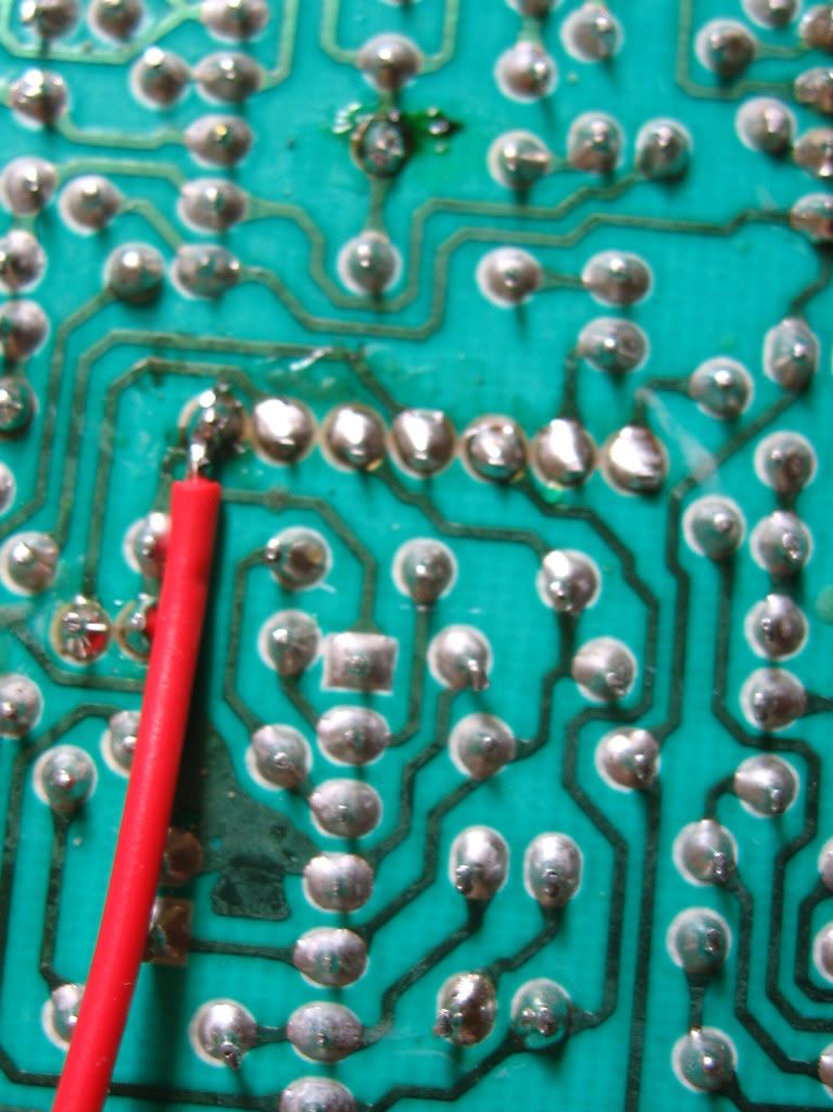
3. Solder the loose end of this wire to the pad in the picture. The pad is the end wire on the ribbon wire.
Now the LED will blink to the Rate pot.
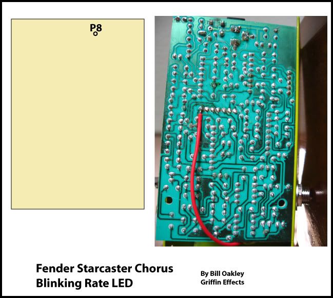
Here's a close up:
I've got a few other things to do to this but I probably won't get to them today.
What you will need:
A piece of wire.
1. Remove the red wire from pad P8 near the top of the board by the DC jack.
2. Add a bit of wire so it will reach around to the point where we are going to solder it. Use some tape or heat shrink tube to put over your solder joint where you connected the new wire so nothing shorts.
3. Solder the loose end of this wire to the pad in the picture. The pad is the end wire on the ribbon wire.
Now the LED will blink to the Rate pot.
Here's a close up:
I've got a few other things to do to this but I probably won't get to them today.
somehow I missed your post. Am excited!endsjustifymeans wrote:Dave's has had some personal touches added by yours truly. It's cooler than decpeticons, which is a hard thing to do.
Also some crunchy goodness was postd you way a coupla days ago
iCEByTes wrote:5 Most Jizz face maker Solo�s , classic Rock music i ever listened.
iCEByTes wrote:Blunt a joint , Take the Touch , Listen this.
-
endsjustifymeans
- Grown Up Punk
- Posts: 19442
- Joined: Tue Feb 10, 2009 4:02 pm
- Location: Ball So Hard University
any chance of a quick demo on the vibrato effect so I know if it's worth it before I potentially blow up my $10 kit? 
dots wrote:society is crumbling because of asshoels like ends
brainfur wrote:I'm having difficulty reconciling my desire to smash the state & kill all white people with my desire for a new telecaster