Hi shortscale! I was hoping someone here could help my electronically ignorant ass.
I've recently been poorly attempting to wire the pickups in my CP jag with the option of running them in series via THIS. I'm pretty certain that I have done exactly as the diagram suggests, but my signal cuts out completely when I move the switches for bridge pup only or try to use series. the bass cut is also adding some nasty loud low end hiss.
Does anyone know what I might have done wrong? just sloppy soldering? does this diagram in fact work?(I'm a little too trusting)
Any help is greatly appreciated
shortscale HALP
Moderated By: mods
-
Cvillethug

- .

- Posts: 15
- Joined: Fri Oct 07, 2011 3:34 am
- Location: Ohio

That diagram looks alright to me but admittedly it's been a while since I've looked into how these switches work. Low-end hiss is probably a bad ground somewhere. Post pictures (or draw a diagram) of exactly what you have, if you can...it'll help immensely 
Edit: Maybe CP jags don't have DP/DT switches? Wouldn't at all surprise me if they used the same switches as AVRIs. In other words, according to that image, this mod wouldn't work for you, if that's the case Someone more knowledgeable than myself will probably be able to answer that.
Edit: Maybe CP jags don't have DP/DT switches? Wouldn't at all surprise me if they used the same switches as AVRIs. In other words, according to that image, this mod wouldn't work for you, if that's the case
Last edited by Dillon on Fri Oct 07, 2011 5:01 pm, edited 2 times in total.

Yes, that wiring design is stupid. Which is why I designed a way to make the pickup switches be completely isolated from whether the S/P switch was in either mode. Posting that diagram was actually my very first post with this community way back in the Jagstang days. Give me a few to dig it up.
euan wrote: I'm running in monoscope right now. I can't read multiple dimensions of meta right now

Do that instead. It actually works and doesn't cut anything out if you move the switches from S/P. You can still cut off both pickups if you switch them both off individually.
My Jag has been wired like this since '06 and it works exactly how you expect it to.
Wait, you still want the bass cut? My version removes it. Bear that in mind.
euan wrote: I'm running in monoscope right now. I can't read multiple dimensions of meta right now
-
Cvillethug
- .
- Posts: 15
- Joined: Fri Oct 07, 2011 3:34 am
- Location: Ohio
That's true, it didn't originally have DPDT switches but I got a pair so I could do this mod.Dillon wrote: Maybe CP jags don't have DP/DT switches? Wouldn't at all surprise me if they used the same switches as AVRIs. In other words, according to that image, this mod wouldn't work for you, if that's the case
I don't really care much too about the bass cut, but unfortunately I'm going to have to order another switch as the remaining stock switch doesn't have all the necessary terminals for the scheme you came up with, Pens. I'm definitely going to try it though, thanks!
Okay, yeah you should install a third DPDT switch there. I have a MIJ Jag which came with them.
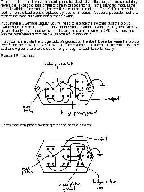
Two things about my diagram, I'm lefty so that's how my switches look to me when I turn the plate over, your switches will be in the opposite order. Just flip the image.
Second, the little V there is supposed to represent the output like a jack, shorthand I always used for my schematic drawings for all of my pedal circuits and shit when I used to do that stuff. That is where you need to take your output line from, on the middle switch there.
Actually, here. I cleaned the image up a bit and reversed the diagram so it now is correct for right handers as you would see the switch plate flipped over.
euan wrote: I'm running in monoscope right now. I can't read multiple dimensions of meta right now
-
Cvillethug
- .
- Posts: 15
- Joined: Fri Oct 07, 2011 3:34 am
- Location: Ohio

This would let you keep the bass cut switch. It would also work with SPDT switches, since it only uses half of each DPDT.
(Edit: It's very similar to the first thing you tried. Maybe a little neater? Dunno.)

Isolate the bridge's negative lead from the claw as per the instructions in your first diagram. I don't know enough about guitars to know if you should do the same with the neck.
Try at your own risk!
The wiring scheme is taken from this Seymour Duncan wiring scheme for PRail pickups and push-pull pots. The diagram is modified from this Seymour Duncan Jaguar diagram. All credit to Seymour Duncan.
(Edit: It's very similar to the first thing you tried. Maybe a little neater? Dunno.)
Isolate the bridge's negative lead from the claw as per the instructions in your first diagram. I don't know enough about guitars to know if you should do the same with the neck.
Try at your own risk!
The wiring scheme is taken from this Seymour Duncan wiring scheme for PRail pickups and push-pull pots. The diagram is modified from this Seymour Duncan Jaguar diagram. All credit to Seymour Duncan.
Last edited by Grant on Sun Oct 09, 2011 11:27 am, edited 15 times in total.


It's a conglomeration of different diagrams made in paint by me in a rush. 
Last edited by Grant on Sun Oct 09, 2011 10:21 am, edited 1 time in total.
The bridge pickup's positive lead and the blue wire are on the same post. The bridge positive lead is always "out" (which is to say, always connected to the center post of the bass cut switch). The only time the bridge is "off" is when the bridge negative lead is connected to neither the neck pickup's positive lead nor ground.
(I also (just now) swapped the order of the key. Switch 1 and switch 2 are now in numerical order.)
Also, I was working with the assumption that Jag pickups are on when their switches are in the down position. Is that the case?
(I also (just now) swapped the order of the key. Switch 1 and switch 2 are now in numerical order.)
Also, I was working with the assumption that Jag pickups are on when their switches are in the down position. Is that the case?
They are normally off when switched down towards the floor. Some people flip the plate around so that they are on towards the floor to prevent accidental switching off while playing, but stock is up for on.
I see now, I didn't notice that most of the signal path is going back up to the posts on the rhythm circuit which is what confused me. I can see what you did there now, but it's hella confusing.
I see now, I didn't notice that most of the signal path is going back up to the posts on the rhythm circuit which is what confused me. I can see what you did there now, but it's hella confusing.
euan wrote: I'm running in monoscope right now. I can't read multiple dimensions of meta right now
I used this Seymour Duncan Jaguar diagram as a base. That isn't how Jags are usually wired? I totally wouldn't know.
I just dropped the PRail switching (normally push-pulls) into the Jag's control cavity.
I just dropped the PRail switching (normally push-pulls) into the Jag's control cavity.
Dude, that diagram is blowing my mind right now. I cannot find a signal path for the condition of having lead circuit, neck off, bridge on. How the fuck does that signal get to the volume pot from there? I'm referencing the SD diagram you linked.
I dunno, I threw all of that out when I designed my switching, and haven't seen stock in seriously 6 years.
Also, it seems like that is backwards, it's like the switches are "ON" when switched towards the floor, based on the choke switch. WTF I'm going to have to study this more.
I dunno, I threw all of that out when I designed my switching, and haven't seen stock in seriously 6 years.
Also, it seems like that is backwards, it's like the switches are "ON" when switched towards the floor, based on the choke switch. WTF I'm going to have to study this more.
euan wrote: I'm running in monoscope right now. I can't read multiple dimensions of meta right now
Pens wrote:Yeah, it's like the neck always has a path to the tip even if it's "off". And I still cannot see any path for signal for the bridge pup unless the neck pup is off. WTF.
When switch 2 is up, bridge negative is connected to ground by way of the yellow wire. Bridge positive is soldered to the same post as the blue wire. The blue wire is wired to the bass cut switch, which is wired through the tone, to the volume, to the rhythm circuit switch, to the tip of the jack.
When switch 2 is up, switch 1 determines is if the neck signal is following the same path in parallel or not at all. The neck is always grounded (via the yellow wire running to the solder on the back of the volume pot (which I assume means it's going to ground)).
When switch 2 is down, bridge negative is lifted from ground, and is instead connected to the purple wire. If switch 1 is also down, then the purple wire is connected to neck positive, which connects the two pickups in series. If switch 1 is up, then the neck positive is connected to the blue wire, which goes to the bass cut switch and onwards. If switch 1 is up, the purple wire isn't connected to anything, the bridge negative isn't grounded, and the bridge pickup is off.
---
The rhythm switch is labeled "neck pickup on-off switch" in Seymour Duncan's diagram. When the rhythm switch is in the up position (towards the ceiling), neck positive is connected to the rhythm pots, which, because the switch is up, are connected to the tip. When the rhythm switch is in the down position, the neck's positive is sent to switch 1. In the down position, the tip is connected to the volume pot, which is connected to the tone pot, which is connected to the bass cut switch.
I think. I've never actually done this.
Last edited by Grant on Sun Oct 09, 2011 10:19 am, edited 1 time in total.
Right, I was referring to the SD diagram, but I see what you are saying. However, in your version, if all switches are flipped down, the bridge negative is connected to neck positive, but so is bridge postive. That's not series, series involves always grounding bridge negative, then flipping between having neck negative either grounded (parallel) or to bridge positive (series) so that they form one giant pickup. Your signal is always going to come off of neck positive. The trick is being able to switch neck pos off but put bridge pos back to the signal line without killing the signal.Grant wrote:Pens wrote:Yeah, it's like the neck always has a path to the tip even if it's "off". And I still cannot see any path for signal for the bridge pup unless the neck pup is off. WTF.
When switch 2 is up, bridge negative is connected to ground by way of the yellow wire. Bridge positive is soldered to the same post as the blue wire. The blue wire is wired to the bass cut switch, which is wired through the tone, to the volume, to the rhythm circuit switch, to the tip of the jack.
Maybe I'm reading it wrong, but that's what I'm seeing there.
euan wrote: I'm running in monoscope right now. I can't read multiple dimensions of meta right now
This computer has gimp; I was able to clean up the diagram a bit.
If both switches are flipped down, the neck positive is connected to the bridge negative. The bridge positive is connected only to the blue wire to the bass cut.Pens wrote:Right, I was referring to the SD diagram, but I see what you are saying. However, in your version, if all switches are flipped down, the bridge negative is connected to neck positive, but so is bridge postive.
In this scheme, the order of the pickups in series is ground->neck->bridge->out. Neck negative is grounded (yellow), neck positive (red) goes to bridge negative (via the purple jumper), bridge positive goes to tip (blue).That's not series, series involves always grounding bridge negative, then flipping between having neck negative either grounded (parallel) or to bridge positive (series) so that they form one giant pickup. Your signal is always going to come off of neck positive.
Why?Your signal is always going to come off of neck positive.
Neck positive is off when switch 1 is down. Bridge pos is always in the lead circuit signal line. There are no instances in the which the (overall) signal would be cut, unless I'm way, way off mark here.The trick is being able to switch neck pos off but put bridge pos back to the signal line without killing the signal.
Last edited by Grant on Sun Oct 09, 2011 10:22 am, edited 1 time in total.