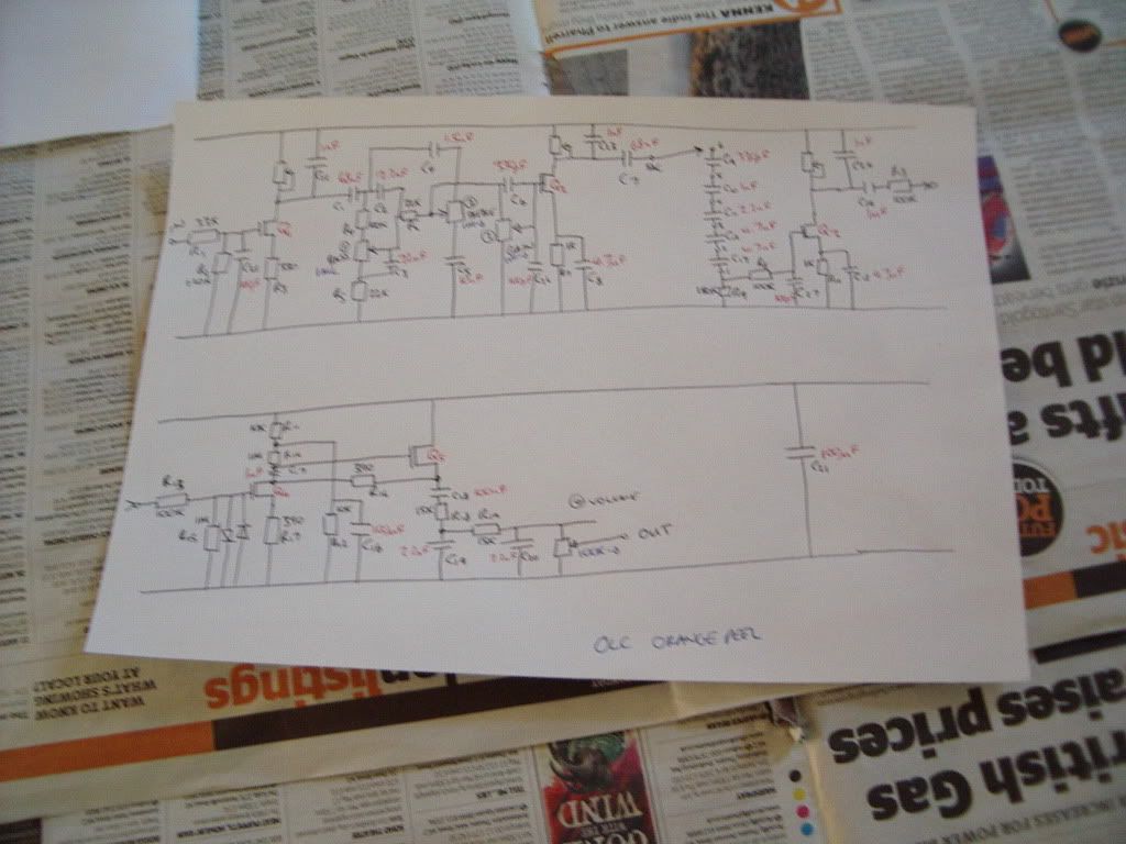
OLC Orange Peel Build (done)
Moderated By: mods
-
mewithoutus

- .

- Posts: 1246
- Joined: Sun Apr 22, 2007 7:46 am
- Contact:


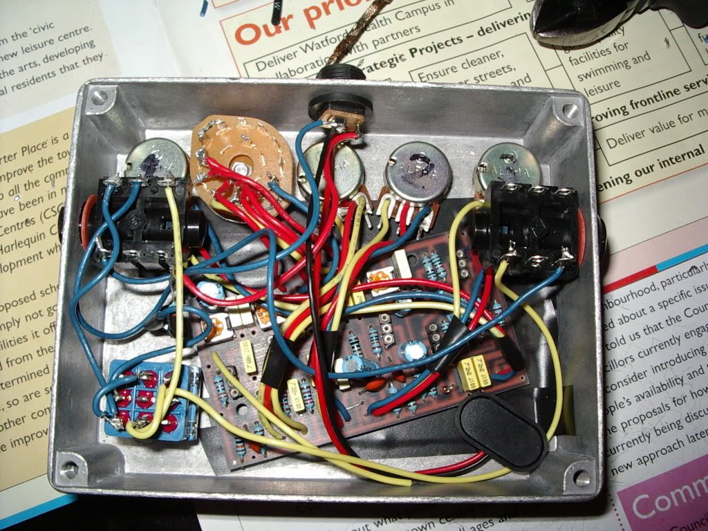
Cool. With mine, I think I just let the wires hold the circuit board in place. The wires were stiff & plentiful enough, the board small & light enough, and it didn't seem to be in danger of shorting against anything. I put a couple small slabs of corrugated cardboard on opposite sides of the battery (or was it on one side?) and these "crushed" just enough to hold the battery in place when I screwed the box closed. I bought standoffs, but couldn't be bothered to install them. I guess you'd have to glue them in, unless you want screw heads on the front of the box.
You're gonna love that pedal once it's done. I'm really curious about that 6-way control.
You're gonna love that pedal once it's done. I'm really curious about that 6-way control.
-
mewithoutus
- .
- Posts: 1246
- Joined: Sun Apr 22, 2007 7:46 am
- Contact:
about the flux-
when building the superfuzzes, i was going through tips like mad with the new lead free solder. wtf man, i didnt know why.
so i tried RMA (resin mild activated flux) solder instead of RA (resin activated) and it was better, but the tips still got eaten up.
so i tired no clean flux solder (2.5% flux) and it is way better. the tips dont get eaten up and it solders great.
i dont know why, but it seems like the regular RA and RMA flux was just eating those tips up.
i got some tip cleaner and tinner from radioshack, and the cleaner is acid based, so that ate up tips too.
try no clean solder and see if that helps.
rich people say fuck yeah hey hey
heavium wrote:grow a bat army in my room and train them to attack when someone comes in
-
Ninja Mike 808

- .
- Posts: 1643
- Joined: Mon Jan 14, 2008 10:06 pm
- Location: DFW
- Contact:
This is why I buy cheap ass irons, cause when the tip is done, I'm not that mad...mewithoutus wrote:about the flux-
when building the superfuzzes, i was going through tips like mad with the new lead free solder. wtf man, i didnt know why.
so i tried RMA (resin mild activated flux) solder instead of RA (resin activated) and it was better, but the tips still got eaten up.
so i tired no clean flux solder (2.5% flux) and it is way better. the tips dont get eaten up and it solders great.
i dont know why, but it seems like the regular RA and RMA flux was just eating those tips up.
i got some tip cleaner and tinner from radioshack, and the cleaner is acid based, so that ate up tips too.
try no clean solder and see if that helps.
-
mewithoutus
- .
- Posts: 1246
- Joined: Sun Apr 22, 2007 7:46 am
- Contact:
sorry but thats a terrible reason to buy a cheap iron. tips can be replaced and knowing how to solder correctly will contribute to your tips life.
before switching to lead free solder, the tip i used in my soldering iron was in there for abot 3 years and it was still perfectly good before i switched it out to a lead free tip.
and when it comes to soldering, the difference between a crappy iron and a good iron is HUGE.
before switching to lead free solder, the tip i used in my soldering iron was in there for abot 3 years and it was still perfectly good before i switched it out to a lead free tip.
and when it comes to soldering, the difference between a crappy iron and a good iron is HUGE.
rich people say fuck yeah hey hey
heavium wrote:grow a bat army in my room and train them to attack when someone comes in

-
Ninja Mike 808
- .
- Posts: 1643
- Joined: Mon Jan 14, 2008 10:06 pm
- Location: DFW
- Contact:
I tried to replace a tip once, but I assume that the heat changed it so that the replacement tip couldn't fit at all...mewithoutus wrote:sorry but thats a terrible reason to buy a cheap iron. tips can be replaced and knowing how to solder correctly will contribute to your tips life.
before switching to lead free solder, the tip i used in my soldering iron was in there for abot 3 years and it was still perfectly good before i switched it out to a lead free tip.
and when it comes to soldering, the difference between a crappy iron and a good iron is HUGE.

-
Mike

- I like EL34s
- Posts: 39170
- Joined: Thu Apr 20, 2006 8:30 am
- Location: Edinburgh, Scotland
- Contact:
Eh? They have a hole you insert the wire into from below and solder at the top to the ring contact.aen wrote:I HATE THOSE KIND OF POTS! Ugh, I always got these ones with little loops on the lugs so all you had to do was fold the wires over and solder. NOw I have like 200 of those "3 stabber" pots and my shit is ALL KINDS of fucked up.
ohaha. I did that onnce, but my shit grounded out on the case, I guess I never tried again.Mike wrote:Eh? They have a hole you insert the wire into from below and solder at the top to the ring contact.aen wrote:I HATE THOSE KIND OF POTS! Ugh, I always got these ones with little loops on the lugs so all you had to do was fold the wires over and solder. NOw I have like 200 of those "3 stabber" pots and my shit is ALL KINDS of fucked up.
High quality, low popularity Ecstatic Fury
-
euan

- partynerd!
- Posts: 27589
- Joined: Sat Jan 06, 2007 3:52 pm
- Location: People's Republic of Irnbruikstan
This is also why I dont do that. There is very little clearance and the solder goes through the otheside.aen wrote:ohaha. I did that onnce, but my shit grounded out on the case, I guess I never tried again.Mike wrote:Eh? They have a hole you insert the wire into from below and solder at the top to the ring contact.aen wrote:I HATE THOSE KIND OF POTS! Ugh, I always got these ones with little loops on the lugs so all you had to do was fold the wires over and solder. NOw I have like 200 of those "3 stabber" pots and my shit is ALL KINDS of fucked up.

euan
-
Mike
- I like EL34s
- Posts: 39170
- Joined: Thu Apr 20, 2006 8:30 am
- Location: Edinburgh, Scotland
- Contact:
Insulation tape underneath the holes on the inside if you're worried your joints are too proud.aen wrote:ohaha. I did that onnce, but my shit grounded out on the case, I guess I never tried again.Mike wrote:Eh? They have a hole you insert the wire into from below and solder at the top to the ring contact.aen wrote:I HATE THOSE KIND OF POTS! Ugh, I always got these ones with little loops on the lugs so all you had to do was fold the wires over and solder. NOw I have like 200 of those "3 stabber" pots and my shit is ALL KINDS of fucked up.


-
Ninja Mike 808
- .
- Posts: 1643
- Joined: Mon Jan 14, 2008 10:06 pm
- Location: DFW
- Contact:
-
Ninja Mike 808
- .
- Posts: 1643
- Joined: Mon Jan 14, 2008 10:06 pm
- Location: DFW
- Contact: