Posted: Fri May 09, 2008 11:03 pm
INtense is definitely the word for it. I actually have worn out the tip of my original iron doing this build. It started to eat itself.
This is why I buy cheap ass irons, cause when the tip is done, I'm not that mad...mewithoutus wrote:about the flux-
when building the superfuzzes, i was going through tips like mad with the new lead free solder. wtf man, i didnt know why.
so i tried RMA (resin mild activated flux) solder instead of RA (resin activated) and it was better, but the tips still got eaten up.
so i tired no clean flux solder (2.5% flux) and it is way better. the tips dont get eaten up and it solders great.
i dont know why, but it seems like the regular RA and RMA flux was just eating those tips up.
i got some tip cleaner and tinner from radioshack, and the cleaner is acid based, so that ate up tips too.
try no clean solder and see if that helps.
I tried to replace a tip once, but I assume that the heat changed it so that the replacement tip couldn't fit at all...mewithoutus wrote:sorry but thats a terrible reason to buy a cheap iron. tips can be replaced and knowing how to solder correctly will contribute to your tips life.
before switching to lead free solder, the tip i used in my soldering iron was in there for abot 3 years and it was still perfectly good before i switched it out to a lead free tip.
and when it comes to soldering, the difference between a crappy iron and a good iron is HUGE.
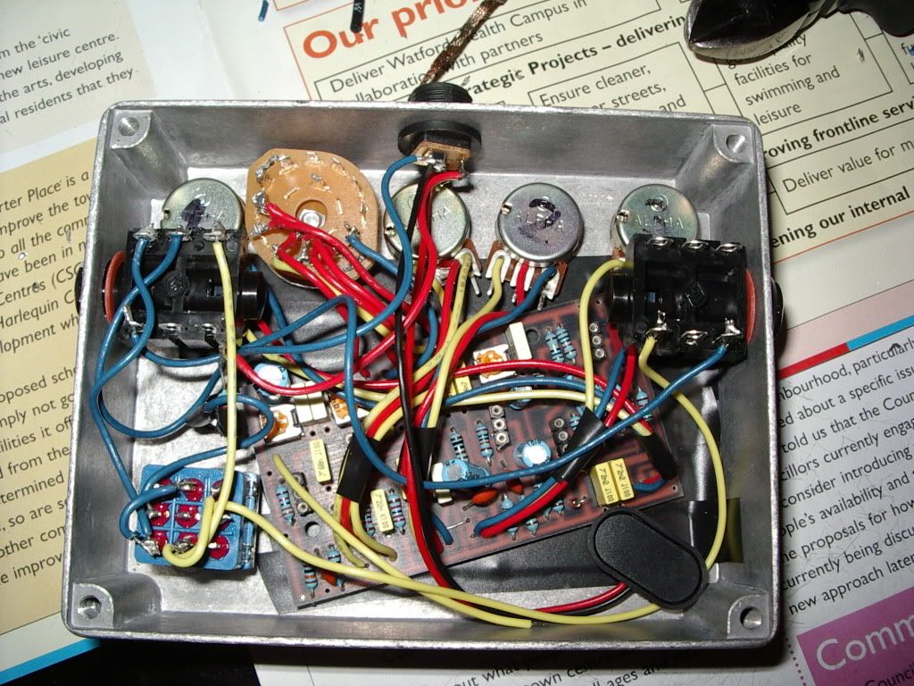
Eh? They have a hole you insert the wire into from below and solder at the top to the ring contact.aen wrote:I HATE THOSE KIND OF POTS! Ugh, I always got these ones with little loops on the lugs so all you had to do was fold the wires over and solder. NOw I have like 200 of those "3 stabber" pots and my shit is ALL KINDS of fucked up.
ohaha. I did that onnce, but my shit grounded out on the case, I guess I never tried again.Mike wrote:Eh? They have a hole you insert the wire into from below and solder at the top to the ring contact.aen wrote:I HATE THOSE KIND OF POTS! Ugh, I always got these ones with little loops on the lugs so all you had to do was fold the wires over and solder. NOw I have like 200 of those "3 stabber" pots and my shit is ALL KINDS of fucked up.
This is also why I dont do that. There is very little clearance and the solder goes through the otheside.aen wrote:ohaha. I did that onnce, but my shit grounded out on the case, I guess I never tried again.Mike wrote:Eh? They have a hole you insert the wire into from below and solder at the top to the ring contact.aen wrote:I HATE THOSE KIND OF POTS! Ugh, I always got these ones with little loops on the lugs so all you had to do was fold the wires over and solder. NOw I have like 200 of those "3 stabber" pots and my shit is ALL KINDS of fucked up.
Insulation tape underneath the holes on the inside if you're worried your joints are too proud.aen wrote:ohaha. I did that onnce, but my shit grounded out on the case, I guess I never tried again.Mike wrote:Eh? They have a hole you insert the wire into from below and solder at the top to the ring contact.aen wrote:I HATE THOSE KIND OF POTS! Ugh, I always got these ones with little loops on the lugs so all you had to do was fold the wires over and solder. NOw I have like 200 of those "3 stabber" pots and my shit is ALL KINDS of fucked up.
my god, that looks immense. this is so far beyond my skills. cheers, mike!Mike wrote:
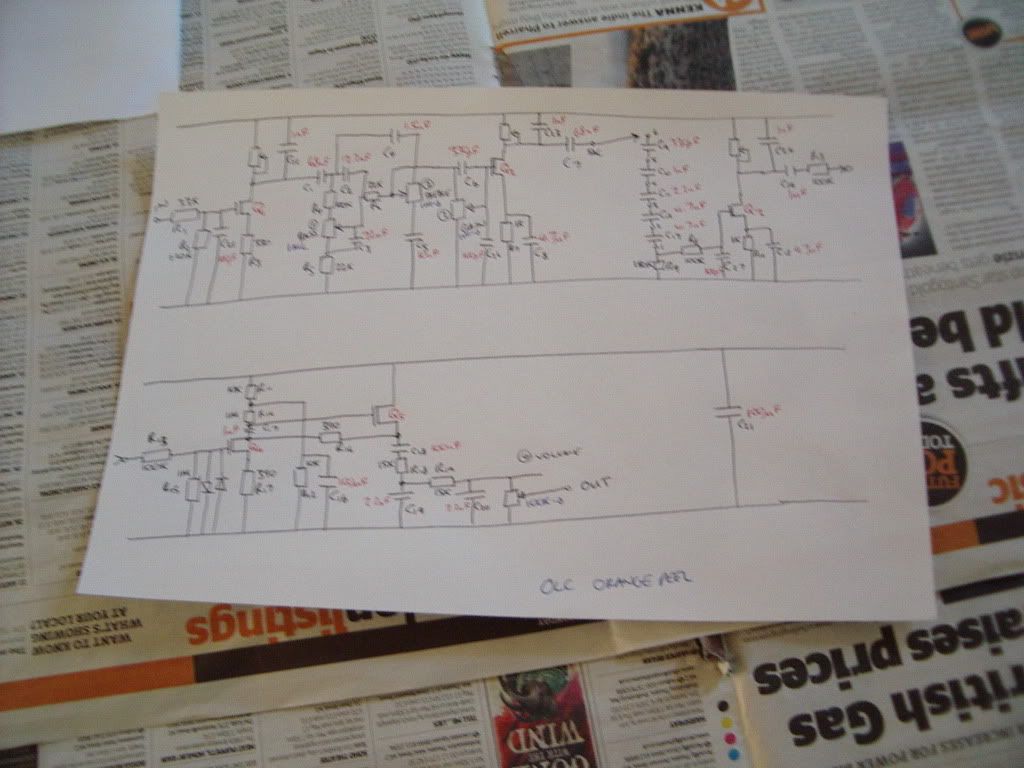
Wow, nice work. With something that complex, it's got to be aggravating looking for a bug.Mike wrote:Schematic reverse engineered from the PCB layout diagrams for help with debug.