Page 2 of 2
Posted: Tue Dec 15, 2009 12:32 pm
by cobascis
NickS wrote:cobascis wrote:Can someone sketch a proper schematic outta this? This should be all I need to know, I need to find out wtf those diodes are so I know what to order. Also, how can I wire this with standard DPDT switches?
thanks
OK, so they are zener diodes, that makes sense - we need to know what value though, so below the 55C there should be more info, like "3v3" or whatever, which is the clamp voltage of the zener.
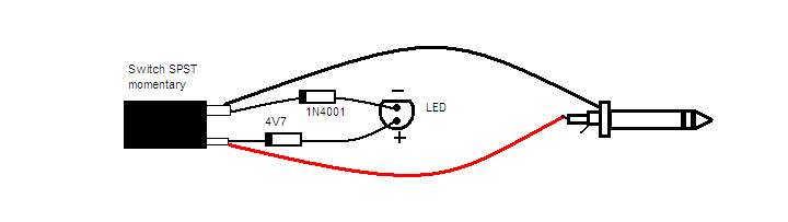
Those little button switches will be momentary action (non-latching), so you need a momentary action stomp switch, almost certainly press-to-make, SPST (or a broken DPDT that doesn't latch any more).
Can you tell us which parts of the jack plug the wires go to? I would guess black is sleeve, but tip or ring is important if you want your switch to switch only the channel.
black is sleeve and the others don't matter as I understand it, if it's flipped, it's flipped: just gotta switch em back. I can't find anyway to buy a 5v6 diode. Also, what gauge wire should I use, and DPDT switches won't work?
Posted: Tue Dec 15, 2009 2:54 pm
by NickS
5v6 500mW zener at Digikey:
http://search.digikey.com/scripts/DkSea ... -3846-1-ND
Wire gauge doesn't really matter.
Switch poles/throw don't *really* matter, but it looks to me like this needs a momentary action switch; wire up to be normally open, push to close.
http://www.smallbearelec.com/ - search for "switch momentary"
Another way to get to your 5.6V drop, near enough, is to get a 4.7V zener (Small Bear do 4.7V 1W) and put another diode in series with the LED to drop another 0.6-0.8V.

Posted: Tue Dec 15, 2009 10:32 pm
by cobascis
Posted: Wed Dec 16, 2009 2:48 am
by cobascis
do you think I could jam all this into this guy?
http://www.smallbearelec.com/Detail.bok?no=49
thanks for all the help.
Posted: Wed Dec 16, 2009 7:07 am
by Zack
yeah, those small bear parts should be fine. obviously, you'll have more wire than you need but for future projects it's good to never run out.
Posted: Wed Dec 16, 2009 9:25 am
by NickS
Goots. wrote:yeah, those small bear parts should be fine. obviously, you'll have more wire than you need but for future projects it's good to never run out.
What he said.
I put a couple of labels on the diagram, though you'd probably have to clear your internet cache or click for the bigger view to see them.
Posted: Wed Dec 16, 2009 1:08 pm
by cobascis
thanks a lot nick, how would I coordinate the 2 channel (2 switch) and I think I'm going with the 4.7 zener from smallbear, if it's just as effective, how would that change up the schematic?
Posted: Wed Dec 16, 2009 1:35 pm
by NickS
cobascis wrote:thanks a lot nick, how would I coordinate the 2 channel (2 switch)
Non comprende, señor. Tell me what you're trying to do, in more detail? I thought you just wanted a channel switch on its own, on your pedal board?
and I think I'm going with the 4.7 zener from smallbear, if it's just as effective, how would that change up the schematic?
To maintain the voltage drop at about the same level, stick a 1N4001 or similar in series with the LED.
Posted: Wed Dec 16, 2009 3:37 pm
by cobascis
NickS wrote:cobascis wrote:thanks a lot nick, how would I coordinate the 2 channel (2 switch)
Non comprende, señor. Tell me what you're trying to do, in more detail? I thought you just wanted a channel switch on its own, on your pedal board?
and I think I'm going with the 4.7 zener from smallbear, if it's just as effective, how would that change up the schematic?
To maintain the voltage drop at about the same level, stick a 1N4001 or similar in series with the LED.
[/quote
Sorry -- I wasn't clear. I want the reverb switch to be included, too. It would be a channel switch and a reverb switch. What does this change?
Posted: Wed Dec 16, 2009 3:57 pm
by NickS
cobascis wrote:Sorry -- I wasn't clear. I want the reverb switch to be included, too. It would be a channel switch and a reverb switch. What does this change?
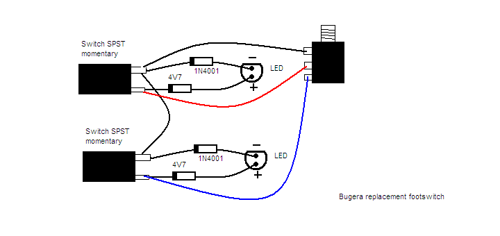
You want to copy the Bugera switch but in your own box? OK, you'll need two of everything except the box and the jack - two switches, two LEDs, two 4.7V Zeners and two 1N4001s. Copy the existing diagram, but attach the wire shown as red to the other tag on the jack. I'll knock up a diagram in a moment.
I guess it would be a good idea to use a jack socket on the box and use an ordinary stereo lead to connect the box to the amp. That way you don't have to worry about rolling up yards of cable when you pack away your pedalboard.
Posted: Wed Dec 16, 2009 4:17 pm
by cobascis
NickS wrote:cobascis wrote:Sorry -- I wasn't clear. I want the reverb switch to be included, too. It would be a channel switch and a reverb switch. What does this change?
You want to copy the Bugera switch but in your own box? OK, you'll need two of everything except the box and the jack - two switches, two LEDs, two 4.7V Zeners and two 1N4001s. Copy the existing diagram, but attach the wire shown as red to the other tag on the jack. I'll knock up a diagram in a moment.
I guess it would be a good idea to use a jack socket on the box and use an ordinary stereo lead to connect the box to the amp. That way you don't have to worry about rolling up yards of cable when you pack away your pedalboard.
Yeah, the main idea is that there won't be a solder cable, for transportation purposes. Now I just need to find a suitable enclosure, I assume I'll have to drill it myself.
Parts list so far.
Enclosure
1N4001s (x2) (small bear)?
4.7 zener diode (x2)
wire (any suggestions?)
2 momentary switches (small bear)
stereo jack
stereo cable
Posted: Wed Dec 16, 2009 4:18 pm
by NickS
I know that's the sort of jack socket that's not in favour round here but it's easier to draw.

Posted: Wed Dec 16, 2009 9:37 pm
by cobascis
Thanks alot, mate. So the 1N4001 is another diode, is that getting the 4.7 value up to the 5.6? Or an entirely different purpose?
Posted: Wed Dec 16, 2009 10:22 pm
by NickS
Yes, that's just adding another 0.7V.
Posted: Wed Dec 16, 2009 10:29 pm
by cobascis
shweet. whole project will be about $25. after I'm going to true bypass mod a behringer big muff--should be simple. 3dpdt and I think I can follow this dudes schematic, though for a diff pedal.
http://www.freestompboxes.org/viewtopic.php?f=11&t=408
Posted: Fri Jan 08, 2010 2:07 pm
by NickS
Pardon the necromancy, but - Cobascis, did you do any of this?