Page 2 of 4
Posted: Wed Feb 24, 2010 2:40 pm
by matt.dines
endsjustifymeans wrote:matt.dines wrote:man your such an asset to this site!
understatement.
+1000!!!
Posted: Wed Feb 24, 2010 2:41 pm
by Mike
endsjustifymeans wrote:Mike wrote:Yeah the A/B was designed for Ends, I believe it has a Saltbooster on/off switch, an A OR B switch and an A AND B switch. Basically it's routing one signal, the input through an optional Saltbooster and then to either amp A, amp B or amp A and Amp B
Works a charm. Love that pedal, really increased the versatility of my Mig.
Lest we forget FilterCap's crucial input to get it working on the Amp side though. He saved our bacon there!
Posted: Wed Feb 24, 2010 2:41 pm
by endsjustifymeans
Mike wrote:endsjustifymeans wrote:Mike wrote:Yeah the A/B was designed for Ends, I believe it has a Saltbooster on/off switch, an A OR B switch and an A AND B switch. Basically it's routing one signal, the input through an optional Saltbooster and then to either amp A, amp B or amp A and Amp B
Works a charm. Love that pedal, really increased the versatility of my Mig.
Lest we forget FilterCap's crucial input to get it working on the Amp side though. He saved our bacon there!
That he did, I owe both you guys.
Posted: Wed Feb 24, 2010 2:42 pm
by Mike
Pish posh, it was a really fun project. I like designing stuff like that and Owen's switcher for his OCD and Peavey Classic 30.
Posted: Wed Feb 24, 2010 2:49 pm
by matt.dines
ohhh mike i gots a mod i wanna put past you
its for a hax ring mod
i wanna put a killswitch in there
but instead of killing the whole signal it just gives you a clean guitar signal
for glitchy coolness

Posted: Wed Feb 24, 2010 2:51 pm
by Mike
Ah I don't mod other people's pedals mate, I would probably build such a thing into an external pedal which has the HAX in a loop and blends back in some Clean signal.
Posted: Wed Feb 24, 2010 2:55 pm
by matt.dines
i really wanted to put a mod past you really!
i would do it but i wanted to see if you think it would work!
if thats cool,
im round my dads tomorrow
so if i could send you a diagram for you to check over that would be cool,
cheers,
matt
Re: Veroboard Layouts for the hobbyist
Posted: Sat Feb 27, 2010 10:53 pm
by Mustang Melx
Mike wrote:I figure these might be useful to some people here, I'll add them as I come across them and/or design them.
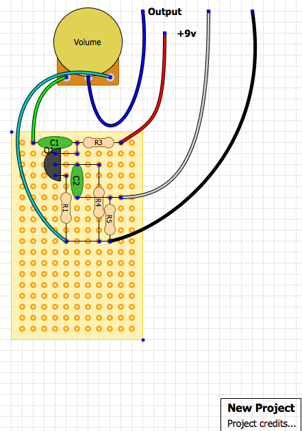
Hey Mike, I built this over the last couple of days and it took me ages to figure out why it wasn't working...


C1, the polarity should be the other way.
C3, needs to come down another row to 'F'
and I think the green wire should go to 'fuzz 1' not 'fuzz 3'
lol, that was a hell of a nightmare for a novice builder diy-er, but I leaned a lot from it!!
p.s. that 2N5088 bazz fuzz sounds fucking great!!
Posted: Sun Feb 28, 2010 4:23 am
by sp3k

This might help noobs like me, took it from here, really helpful site:
http://www.beavisaudio.com
Posted: Wed Jul 14, 2010 3:38 pm
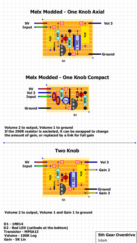
by Mustang Melx
Here's a great little Overdrive/Distortion, I like it a lot. sounds a bit dist+ish to me.
Posted: Thu Jul 15, 2010 11:09 am
by Mike
What program are you using to make those layouts? It looks way nicer than DIY Layout Creator on my PC
Posted: Mon Jul 19, 2010 2:01 pm
by Mustang Melx
Mike wrote:What program are you using to make those layouts? It looks way nicer than DIY Layout Creator on my PC
I didn't make them IvIark did, I'll ask him.

I need to start learning to them myself too, so I'll find out.
Posted: Wed Aug 18, 2010 1:50 pm
by Mike
More for anyone interested:
Way Huge Swollen Pickle (original)
Germanium and Silicon Tonebenders (Germanium is positive ground)
Suhr Riot (great sounding Marshall Guv'nor Inspired High Gain Overdrive/Distortion)
Muffs!
Posted: Sun Oct 17, 2010 2:50 pm
by Bacchus
I was wondering how to read veroboard layouts (more put of curiosity than any ambition to build anything soon) and came across this site that has fair whack of information on it. I thought it was pertinent and decided to post it here:
http://www.zen22142.zen.co.uk/index.html
Re: Veroboard Layouts for the hobbyist
Posted: Sun Oct 17, 2010 3:15 pm
by SKC Willie
Yes, I was wondering how to read these as well. Do you connect everything that is on row a together and then everything that is on the columns together? Or is it not that easy? And what is that red square with a dot in it?
Posted: Wed Oct 27, 2010 6:54 pm
by SKC Willie
sooo, I think my question was missed. but I don't understand how to read veroboard diagrams.
If I were to make a point to point layout for the salt booster, would this be correct?
Posted: Wed Oct 27, 2010 7:42 pm
by Mages
veroboard is a special kind of printed circuit board with rows of holes connected together. so all the holes in each row are connected unless you cut the trace (as mike indicates here with the red squares).
more here:
http://en.wikipedia.org/wiki/Stripboard
Posted: Thu Oct 28, 2010 1:54 am
by 24HRS2MDNT
[quote="portugalwillie"]sooo, I think my question was missed. but I don't understand how to read veroboard diagrams.
+1 Same here.
Cool thread.
Posted: Tue Mar 15, 2011 4:58 am
by tambey
Tq Mike,
Just like to ask you. Where do the wire goes (switch P on Riot vero layout). And maybe some drawing would be great. Thank you again and sorry for my noob question.
Posted: Sun May 01, 2011 5:43 pm
by jdrier21
Wow. All these are amazing diagrams. U win my friend. I think I know what my next summer project is going to be
