This pedal sounds great and works great when I run a salt booster in front of it.
I'm convinced that I've got a resistor value wrong somewhere but I'm not really sure how to go about tracking it down.
Building Pedals
Moderated By: mods
-
SKC Willie

- Bunk Ass Fuck
- Posts: 3465
- Joined: Thu Nov 05, 2009 5:46 pm
- Location: Columbia, MO
- Contact:
-
SKC Willie
- Bunk Ass Fuck
- Posts: 3465
- Joined: Thu Nov 05, 2009 5:46 pm
- Location: Columbia, MO
- Contact:
So, after checking and double checking resistors, everything is good. I have replaced R24 with a 12K and R23 with a 3.9K and it gave me more fuzz but the problem persist.
After working the pedal again, I realized I'm not getting any sound when the sustain is turned to 0. I'm guessing that is significant but after checking again, I still can't figure out what is causing the issue. Any help/ideas would be appreciated.
After working the pedal again, I realized I'm not getting any sound when the sustain is turned to 0. I'm guessing that is significant but after checking again, I still can't figure out what is causing the issue. Any help/ideas would be appreciated.
twitter.com/skcwillie
follow me . . . . you won't
follow me . . . . you won't


-
Concretebadger

- .

- Posts: 2111
- Joined: Sat Apr 14, 2012 5:29 pm
- Location: Leeds Leeds LEEDS
- Contact:
I've got the bypass wiring fine but there's a big dollop of solder lying across two of the copper tracks on my board, so I'm guessing it's shorting something out. I don't have any desoldering braid or a solder sucker, so is there any other way of removing it? Worst of all, the two components being shorted are a diode and an electrolytic cap - two components that are most sensitive to the high temperature of my iron. I can't get the sodding lump of solder to shift, and can't cut it off either. 
Do you have any spare braid-screened cable you could cut braid off?
If not, melt the blob and rap the board sharply on the worktop to flick the solder off.
TBH, though, if you're going to do anything much with kits, get a solder sucker.

£2.25 free delivery at Amazon
If not, melt the blob and rap the board sharply on the worktop to flick the solder off.
TBH, though, if you're going to do anything much with kits, get a solder sucker.
£2.25 free delivery at Amazon
-
SKC Willie
- Bunk Ass Fuck
- Posts: 3465
- Joined: Thu Nov 05, 2009 5:46 pm
- Location: Columbia, MO
- Contact:
I did my first two builds with a solder "sucker" and then I spent $5 on a cheapie from Radioshack and I cannot stress how much it has helped. Fixing stuff like this, experimenting with different values, and just generally cleaning up my poor soldering has been so much easier.
Other than that, I aslo have a small hand saw that I use to break apart solder joints and clean up any potential cross overs on my stripboard.
I use one like this and while it's probably not as nice as the spring loaded ones, it does the job fine.
Ebay Link
Other than that, I aslo have a small hand saw that I use to break apart solder joints and clean up any potential cross overs on my stripboard.
I use one like this and while it's probably not as nice as the spring loaded ones, it does the job fine.
Ebay Link
Last edited by SKC Willie on Sat Mar 16, 2013 6:09 pm, edited 1 time in total.
twitter.com/skcwillie
follow me . . . . you won't
follow me . . . . you won't


Cool I was going to try out the Seamoon kit. IIRC there was some specific setup instructions (knob settings) for getting it working, or at least saw a yourtube vid about it.
Mike wrote:All my LEDs are bright, the blues are bright as all hell.
mezzio13 wrote:JJ makes sweeps look easy and effortless. His nick name should be broom.
-
Concretebadger
- .
- Posts: 2111
- Joined: Sat Apr 14, 2012 5:29 pm
- Location: Leeds Leeds LEEDS
- Contact:
Bitsbox are great for parts - really quick dispatch and seem pretty cheap.
I'm not as impressed with the Tagboard Effects triangle muff layout though - Mike's looks a bit better organised and I made so many mistakes on my first attempt I can't salvage it without botched repairs frying everything due to iron heat.
Am I right in assuming that your first attempt is likely to be a monumental fuck-up that makes you feel really annoyed with yourself? I'm going through that OH SHIT I'M SUCH A MORON RAGEQUIT phase and I'm impatient to have another go and do it better.
Bollocks.
Nah, it doesn't even pass signal. I'm going to rewire the whole works and hope that at least the board is fine.rps-10 wrote:Cool I was going to try out the Seamoon kit. IIRC there was some specific setup instructions (knob settings) for getting it working, or at least saw a yourtube vid about it.
I'm not too annoyed, I sort of expected to make a hames of at least one pedal.

-
Concretebadger
- .
- Posts: 2111
- Joined: Sat Apr 14, 2012 5:29 pm
- Location: Leeds Leeds LEEDS
- Contact:
Duly noted.Mike wrote:I buy in bulk from rapid to get decent rates, I can sort you out
Drop me a pm
I'm trying Mike's layout for my second prototype (the first one failed miserably) and I'm currently poring over this one. I'm guessing from the shapes on the illustration that C1, C8, C13 and C14 are electrolytic caps that need to be orientated in a certain direction, but I can't tell from the layout alone which 'end' of each cap is which.
It's just, that seems a bit more compact than the Tagboard FX layout, and uses fewer board cuts and jumpers.
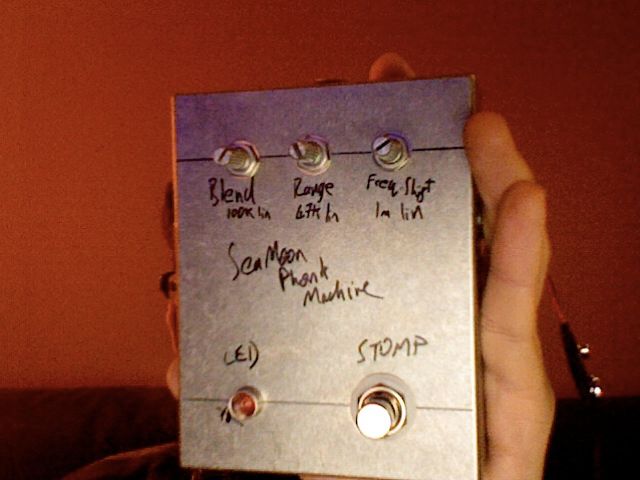
Funk machine build 2 still borked, but workinger.
I was fitturing with it open, trying to spot any obvious shorts. It still wasn't passing signal, but I noticed that with a but of jiggling at the jacks, signal would sometimes pass. So I took both jacks out of the enclosure so that part of the harness was hanging free and it passed signal but was hella fizzy. I played with it a bit and the fizz cleaned up almost completely with the blend knob turned entirely clockwise, but neither of the other two pots did anything at all and the sound was unnaffected apart from the fizz with the blend down.
I was hoping this sounds like a really obvious grounding problem or something. Any ideas?
-
Mike

- I like EL34s
- Posts: 39170
- Joined: Thu Apr 20, 2006 8:30 am
- Location: Edinburgh, Scotland
- Contact:
Shades end - cathode - striped end of capConcretebadger wrote:Duly noted.Mike wrote:I buy in bulk from rapid to get decent rates, I can sort you out
Drop me a pm
I'm trying Mike's layout for my second prototype (the first one failed miserably) and I'm currently poring over this one. I'm guessing from the shapes on the illustration that C1, C8, C13 and C14 are electrolytic caps that need to be orientated in a certain direction, but I can't tell from the layout alone which 'end' of each cap is which.
It's just, that seems a bit more compact than the Tagboard FX layout, and uses fewer board cuts and jumpers.
-
Concretebadger
- .
- Posts: 2111
- Joined: Sat Apr 14, 2012 5:29 pm
- Location: Leeds Leeds LEEDS
- Contact:
Ah, I see. There's a stripe or different colouration printed on the body of the cap, right? I can't make out how or if that polarity is specified on the diagram though...sorry if it's a bit cheeky to ask, but which schematic is that layout based on? If I can work out which components do what, I ought to be able to understand it a bit better (and hopefully won't need to pester you with n00bish questions any more).
The Kit Rae site is a goldmine of info about how various sections of the circuit alter the sound, so I'm trying to identify those in this particular layout's signal path. If that doesn't make sense I can PM you the other diagrams and specs that I'm working from.
The Kit Rae site is a goldmine of info about how various sections of the circuit alter the sound, so I'm trying to identify those in this particular layout's signal path. If that doesn't make sense I can PM you the other diagrams and specs that I'm working from.
-
Concretebadger
- .
- Posts: 2111
- Joined: Sat Apr 14, 2012 5:29 pm
- Location: Leeds Leeds LEEDS
- Contact:
I put my second prototype (based off Mike's Ram's Head with one or two different component values) together, and surprisingly it works. More or less. As in, guitar goes in and sound comes out that sounds Muff-y. I did a quick demo clip but I'll try to do a proper A/B comparison with my '78 IC to see what the differences are. That was set up in a few seconds and I'm not really making much effort to play anything...it was the D.I./headphone output from my Marshall, so doesn't sound quite like it does 'in the room' as it were.
There's a lot of volume on tap and it gets a bit more trebly as the sustain increases but otherwise it sounds surprisingly authentic. Since it's actually functional, I think I'll look for a proper enclosure for it.
There's a lot of volume on tap and it gets a bit more trebly as the sustain increases but otherwise it sounds surprisingly authentic. Since it's actually functional, I think I'll look for a proper enclosure for it.