Page 3 of 3
Posted: Sun Jan 10, 2010 3:02 am
by cobascis
I got it so that the pedal turns on and the led does too (its off before I switch). BUT there is NO bypass tone at all, no sound gets through when it is off. what did I fuck up??? I couldnt figure out with way the switch should be facing so that I can number the poles. 123 was 789?
Posted: Sun Jan 10, 2010 3:06 am
by Will
Pictars?
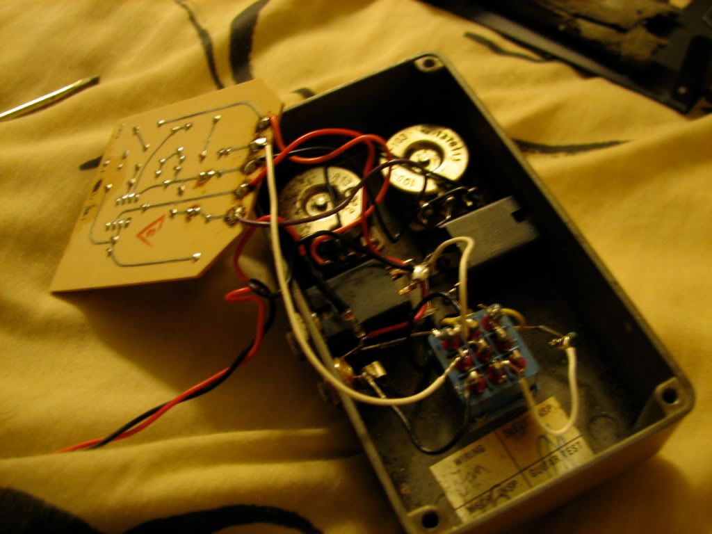
If you're getting effect signal, you're pretty close to there. Need to see the switch, though.
Posted: Sun Jan 10, 2010 3:06 am
by cobascis
Posted: Sun Jan 10, 2010 3:18 am
by Will
It looks fine as far as I can see. You're probably dealing with either a short or a cold solder joint. You've got a lot of uninsulated lead exposed. I'd go back and redo the joints to be a bit tidier and then see where you are.
Posted: Sun Jan 10, 2010 3:27 am
by cobascis
Will wrote:It looks fine as far as I can see. You're probably dealing with either a short or a cold solder joint. You've got a lot of uninsulated lead exposed. I'd go back and redo the joints to be a bit tidier and then see where you are.
So the wiring is correct, just a dead solder? Ill check it out.
Posted: Sun Jan 10, 2010 3:47 am
by cobascis
FUCK. After resoldering some joints the led now doesn't work, and when switch on there is a high pitched whine with no guitar signal.
I suck.
I'll try again tomorrow with any new advice?
Posted: Sun Jan 10, 2010 6:47 am
by Zack
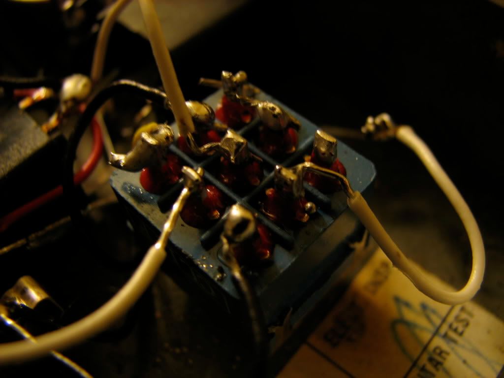
You should try using the layout that earth posted for the 3pdt true bypass. I can't quite tell what your layout is it looks like this to me:
Code: Select all
x-lug 1        x- ?      x-connected to lug 1
x-effect in    x-gtr in  x- connected to ^
x-ground       x-led     x
which would leave ? being output? You should probably have the effect in grounded when the effect is not on. The way you've got it positioned right now, the 3dpt that is, has the connections working as though "lug 1" connects to "?" and when switched "?" connects to "connected to lug 1." This would be the case if I'm labeling your wires correctly. Essentially, you just have the switch rotated 90 degrees the wrong way, adjust it and it'll be 123 on the top row.
you could just have a bad connection with the column on the right, the one where you have a joined connection with two lugs. Is the effect output connected directly to the circuit? If so, then it's not true bypass. Again, I'd recommend just using the diagram posted by earth. If you haven't got a effect out, then move the wire that's in the out jack to the recommended placement of "effect out" and wire an "out" from the outjack.
good luck.
Posted: Sun Jan 10, 2010 7:46 am
by devnulljp
I think you might also need to replace that insulating foam that crumbled away too to stop it shorting out on the case.
blondegraemey did a vid of doing that
Posted: Sun Jan 10, 2010 7:48 am
by Zack
I was under the impression that mxr had cards that they placed in between the circuit & the back of the pedal. My dod clone of the dist+ has a card in it. If you don't have one, a piece of card stock should do the trick.
Posted: Sun Jan 10, 2010 11:15 am
by Mike
The vertical lines on the switch split it into "poles".
Posted: Sun Jan 10, 2010 1:13 pm
by cobascis
I'm under the impression I connected 1 and 4, is this correct? Does it matter if the switch is facing up or down? I won't be able to solder until tonight.
Posted: Sun Jan 10, 2010 10:04 pm
by cobascis
VICTORY. 2 wires just needed to be switched, I neatly resoldered every joint too looks nice inside now. thanks for your help. my bypass is now true. onto the big muff..