Page 3 of 4
Posted: Sun May 01, 2011 7:41 pm
by Bacchus
Earlier today I downloaded all of these and bounced them into the one pdf to make them easier to view.
http://www.megaupload.com/?d=BGO7XNIP
Posted: Sun May 01, 2011 8:26 pm
by gaybear
good job!
Posted: Mon May 02, 2011 12:58 am
by Sloan
I might actually try to put some of this easy looking stuff together...
Posted: Wed May 25, 2011 7:18 pm
by morke666
Howdy folks,
First post, I actually only registered here to thank you guys (and Mike Livesley especially) for the awesome layouts and inspiration you've given me.
I've built several of the layouts here, and I am absolutely blown away by them —how in the name of Cthulhu could I ever live without these tiny machines! They make my bass sound like a tank running over piles of rocks dressed with a light sprinkle of childrens souls' essence. Exactly what I need!
Thanks again!
M.
Posted: Wed Sep 12, 2012 8:08 pm
by SKC Willie
so, these really should be sticked because they're a really cool thing to have on the forum.
I'm working on the meathead and everything seems to be working EXCEPT it's super quiet. I did some google-ing without much luck. When off, the LED is off and the bypass is fine, but on, the volume drops down significantly but if you turn the amp WAY up, the fuzz is working. I'm thinking it's a power issue? Any suggestions?
Posted: Wed Sep 12, 2012 9:57 pm
by SGJarrod
check you tranny pinouts
Posted: Thu Sep 13, 2012 1:32 am
by SKC Willie
SGJarrod wrote:check you tranny pinouts
the soldering on everything is solid. I just sent you a pm explaining everything.
Posted: Thu Sep 13, 2012 9:14 pm
by SKC Willie
so, I built the saltboost and it's the exact same problem. I then changed the LED resistor on the Meat from a 4k7 to a 2k2 and it seems to be louder.
If it's too quiet, is it possible I just need to lessen the resistor value on the LED? To me that wouldn't work because the LED is on the end of the circuit and I don't totally see how decreasing the resistor value would do anything except effect the LED.
what resistor should I be using in front of the LED?
Posted: Thu Sep 13, 2012 10:01 pm
by SGJarrod
4k7 is normal for LEDs...that should not make a difference in the actual curcuit performance thou
Posted: Sat Nov 03, 2012 7:41 pm
by sp3k
Mike wrote:
Would connecting I18 to L3 bypass the tone?
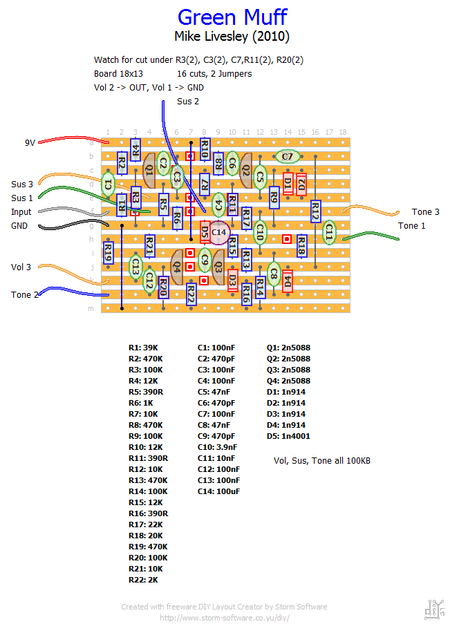
I build one using your layout, love it, probably my favorite muff, and I've tried some expensive ones... The problem is that I can't really use it with bassie chords in a band situation and still ear myself...
Posted: Sun Nov 04, 2012 8:35 am
by Mike
Yup that would do it, you can also to the tone stack mods you mentioned on pm to this
Post them up here
Posted: Sun Nov 04, 2012 4:36 pm
by sp3k
Mike wrote:Yup that would do it, you can also to the tone stack mods you mentioned on pm to this
Post them up here
I actually did this yesterday and it worked. Lots of more mids and volume, the sound isn't the muff sound I love, but it's probably usable with a band now.
The other mod is adding a mids pot, changing c10 to 22nf and r17 for a 25k pot in series with a 1k r.
What do you think would be better for the pot, linear or log?
Posted: Mon Nov 05, 2012 8:53 am
by Mike
Linear will work just fine, either will but that's what I use for a mids pot.
You will find if you add mids than the muff sounds different - the scoop is part of it's signature sound.
Posted: Sun Jan 06, 2013 7:13 pm
by pns
Mike wrote:More for anyone interested:
Way Huge Swollen Pickle (original)
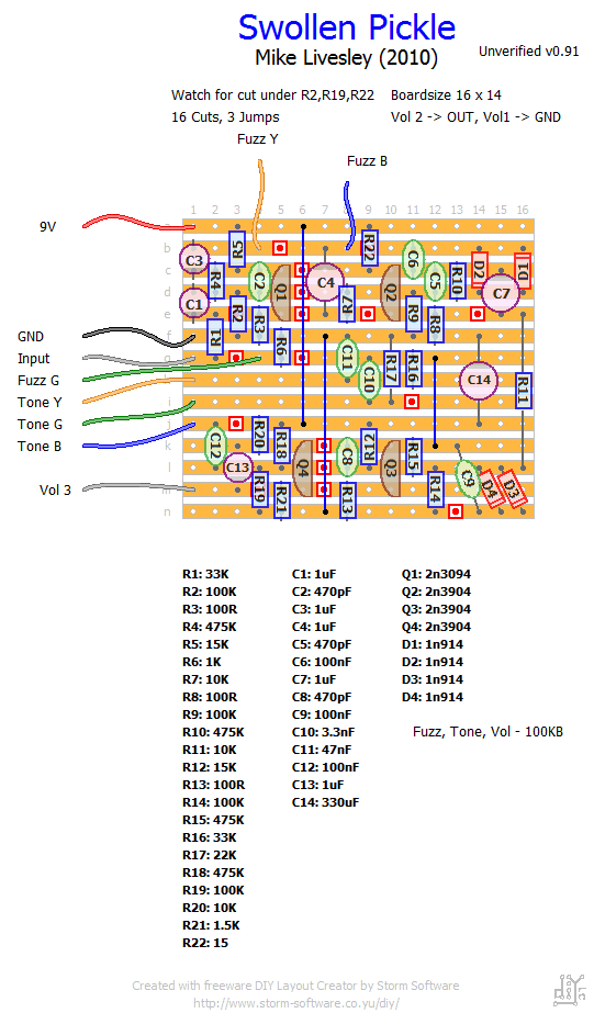
the potentiometer configuration on the swollen pickle vero board layout is confusing me a bit.
can someone please clarify for me please i would be very grateful...
I stuffed and soldered the board but the the configuration on the fuzz and tone potentiometers is a little bit confusing for me.
If you could please clarify what Y G B translates to in terms of "pot leg" 1 2 3. in other words, can i just send any leg on the pots to the board?
or is there a specific leg on the pot that must correlate to what you marked as Y G and B?
The other question is... the tone should be a linear pot right? and the volume and fuzz logarithmic pots?
if you could clarify it would help me with placing the legs on the pots to the right place on the board.
finally, they are all 100k right?
Thanks in advance mates!
Posted: Fri Jan 18, 2013 9:11 am
by luciguci
While we're here, what's the difference between the 2n5088 & MPSA13 Bazz Fuss's?
Posted: Fri Jan 18, 2013 2:42 pm
by SKC Willie
pns wrote:The other question is... the tone should be a linear pot right? and the volume and fuzz logarithmic pots?
I'd imagine you can use either but I'm pretty sure the 100kB means that he's using linear for all pots. Can't help you the Y, G, B issue but I'd imagine Mike will chime in relatively soon.
Posted: Fri Mar 15, 2013 5:36 am
by TheAyatollah
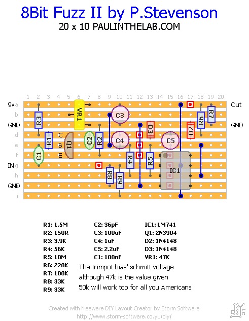
I'm new here, first post. Resurrected from the dead. But, I thought I'd add a few links with lots of great info and layouts.
LOTS of vero layouts here, updated and edited frequently. Excellent off-board wiring tutorial for beginners. Easy to ask questions and get quick replies. Super cool dudes.
http://www.paulinthelab.com/Paul In The Lab, this guy's a wizard and often posts up some cool layouts for music related electronics, and other things. All verified.
This is my current project, it has no controls, I got it from Paul's blog, he designed it himself as a quick circuit and decided to forgo knobs, although there is a bias trimpot on the board. I'm planning on making 2 of these, mainly for use with electric organ. I'll be wiring them up as traditional stompboxes and adding a voltage starve control and perhaps a switch to toggle between two different transistors.
Re: Veroboard Layouts for the hobbyist
Posted: Sun Jun 23, 2013 6:45 pm
by Walnut
Mike wrote:
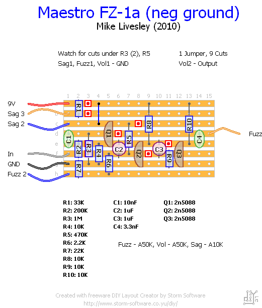
How do I determine the orientation/polarity of C2 and C3? And will I have to bias the transistors? How do I know if I have to when building a pedal? Is that "Fuzz 3" cut off on the right side? Also, has anyone built this yet? How does it sound? I'm curious because the original FZ-1A doesn't have a sag control. Sorry for all the questions, I'm kind of new to pedal building.
Posted: Sun Jun 23, 2013 7:11 pm
by timhulio
God don't build one of these if you're new to pedal building. Get a kit first (something op-amp based) because the FZ-1 really is no fun and neither, to be honest, is vero board.
Posted: Sun Jun 23, 2013 7:15 pm
by Mike
pns wrote:Mike wrote:More for anyone interested:
Way Huge Swollen Pickle (original)
the potentiometer configuration on the swollen pickle vero board layout is confusing me a bit.
can someone please clarify for me please i would be very grateful...
I stuffed and soldered the board but the the configuration on the fuzz and tone potentiometers is a little bit confusing for me.
If you could please clarify what Y G B translates to in terms of "pot leg" 1 2 3. in other words, can i just send any leg on the pots to the board?
or is there a specific leg on the pot that must correlate to what you marked as Y G and B?
The other question is... the tone should be a linear pot right? and the volume and fuzz logarithmic pots?
if you could clarify it would help me with placing the legs on the pots to the right place on the board.
finally, they are all 100k right?
Thanks in advance mates!
I've already labelled them all as 100KB = 100 K Linear
Y = Hot
B = Wiper
G = Ground
Or 3,2,1 if you prefer.