Page 4 of 12
Posted: Tue Oct 12, 2010 1:38 am
by Bill Oakley
portugalwillie wrote:Okay. I've been learning about diodes, capacitors, and resistors. Most of what the Prof is talking about is over my head but no worries, I'm slowly catching on.
My soldering skills are pretty decent. They're not great but I've rewired several guitars (including Jags!) so I have a decent amount of practice, I'm just trying to figure out the best way to lay out all of my parts. Right now I'm getting a little stuck on the points that are not connected to anything. For example on the top circuit I see a capacitor followed by a resistor then the plus sign. Obviously resistors have two ends, so do I just leave one end not connected to anything? If that is that case, should I cut the end off so it doesn't come in contact with anything on accident? And all of the grounds, what should I be grounding them to?
I know these are super noob questions but I am one!
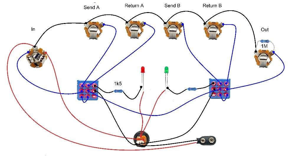
And just out of curiosity, the part of the circuit with the LED is only connected to the other parts of the circuit through the ground, I assume they all need to be grounded to the same place but does that part of the circuit actually effect the tone, or is all of that just for the LED?
See the VR by C11? All points marked VR connect to there. So the ends of R3 and R4 would connect to the positive side of C11.
Same exact thing with all the grounds. They all have to connect together.
For the LED, you need to look online for true bypass switching diagrams. R16 is the Drop Down Resistor which controls how bright your LED is and the LED pad would connect to the positive leg of the LED. The other leg of the LED would connect to the switch. Hence looking online for bypass switching diagrams.
Posted: Tue Oct 12, 2010 2:53 am
by SKC Willie

Would this work?
Posted: Tue Oct 12, 2010 3:13 am
by Bill Oakley
No, you wouldn't want +9v going to the switch. You would want ground there. I mean, I guess you could wire up the LED that way but I just don't like putting 9v on the switch for some reason.
I would do it this way:
True Bypass Switching, LED, Grouded Input
Posted: Tue Oct 12, 2010 3:17 am
by SKC Willie
I found this . . . and the person seemed to know what they're talking about. Second opinion?
Bypass Explanation
Posted: Tue Oct 12, 2010 3:22 am
by Bill Oakley
Yes, I've seen that guys stuff and he is very knowledgeable. Following that will work. By the way, it's the same as in the link I gave you.

Posted: Tue Oct 12, 2010 8:16 am
by Mike
Yeah don't put 9V on the switch. Use the scheme Bill linked. It is the one I use and it is the best.
Posted: Tue Oct 12, 2010 3:16 pm
by SKC Willie
Cool, thanks guys.
today I should be actually drawing a layout for everything and putting it on a bread board.
Posted: Tue Oct 12, 2010 4:19 pm
by SKC Willie
Annnd
Bill, where would recommend buying 3 pdt switches. I wouldn't mind buying 5 or 6 but not if they're selling for $10 a piece. Is there a place that sells them cheaper?
Posted: Tue Oct 12, 2010 4:44 pm
by Bill Oakley
pedalpartsplus.com
Posted: Wed Oct 13, 2010 1:06 am
by SKC Willie
Awesome!
Also, I can't find the integrated circuit JRC 45580 anywhere? I assume the IC1A just means integrated circuit but if I can't find that exact one, is there another I can use?
Seriously, thanks for the help. I know I'm asking questions about everything but I'm just trying to learn everything I can so when I finally start building, it may actually work.
Posted: Wed Oct 13, 2010 1:20 am
by Bill Oakley
Any dual Op-amp will work really.
This may become your new friend:
Octopart
JRC4558
Edit: Actually the jrc4558 octopart search really didn't come up with anything usable.
This is better:
RC4558
Posted: Wed Oct 13, 2010 1:41 am
by SKC Willie
Sweet. Bookparked octopart and pedal parts. Thanks for the info
Posted: Wed Oct 13, 2010 7:35 am
by Mike
You can also sub in lots of low cost IC dual op-amps in place of that if you want to experiment:
TL072
TL082
etc.
Posted: Wed Oct 13, 2010 8:30 pm
by ekwatts
Okay, I'm into the soldering part now, but I'm still a little mystified by the power socket I bought. There are two tags, one longer than the other, and then a metal bit in the centre. Now on the other power socket that was supplied with the kit, there were three tags, one of which appeared to be connected directly to the centre bit of metal. On this one, neither tag appears to be directly connected on the back of the socket, but I can see on the inside that the shorter tag is connected to the middle bit (I think).
Now with the black/negative wires, do I solder them directly to the centre bit of the plug, or the shorter tag? And for the red wires, are they all soldered to the longer tag?
I ask because the red wires were soldered to two different tags in the original schematic, so it's thrown me a little bit. Is it actually possible to simply have all of the red wires soldered to a single tag, and have they split them between two to make it simpler for noobs like me? Or do they genuinely need to not touch?
Posted: Wed Oct 13, 2010 10:26 pm
by ekwatts
Apart from the question of where and how to wire up the power socket, I've soldered everything else up, plugged it in, and...
NOTHING.
Because one of the switches was on, and there was nothing in that loop. Switched it off, and BANG. Works. Tried the loops with a simple patch across each one, and still received glorious rez-o-matic goodness from my Batwing through everything.
Dead chuffed, I am. Proper fucking chuffed. To mintballs. I feel like I've done something worthwhile (yes, I know, it's just a bypass loop).
There's plenty wrong with it; my soldering is wank, the footswitches were drilled so close together it looks like a pisstake (there's an inch between them), power socket isn't wired up, etc, but I'm proud of myself for having followed a piss-simple plan and actually managed to create something.
One question: Why does my soldering iron look like it's on its last legs? The tip has gone all knobbly, and now that it's cooled down, I've noticed it's all wobbly too. It looks like the nib has etched grooves into itself from being stood in my ghetto-ass homemade stand I made this morning (triangle of wood with a coiled metal coathanger) for some bizarre reason. This is the only time I've used it. Looks like I'm going to have to do a bit more practice. And maybe not use that stand. And probably buy a new soldering iron.
Posted: Wed Oct 13, 2010 10:30 pm
by ekwatts
And another thing that just struck me: If I'm leaving the battery clip out then is the red wire from the input jack going to the power supply still necessary?
Posted: Thu Oct 14, 2010 7:48 am
by timhulio
No, and really that wire should be black. You also didn't have to use a stereo jack for the input either.
Posted: Thu Oct 14, 2010 7:51 am
by Mike
Wiring scheme looks weird.
If I'm using a battery clip, I sold the black wire of the battery clip to the large tag (centre negative, ground) of the DC jack, and the red one to the switching power tag (bottom one if the ground tag is on the top), and then the power to the circuit goes from the right lug. This way when a DC jack is plugged in the battery is disconnected from the circuit. Bugger knows why they've connected the 9V output of the battery to the ground loop on that diagram.
What you need to do:
1. Show me the DC jack again so I can ID the ground and 9V lugs for you.
2. Solder a wire from the ground lug to one of the jack grounds, and then connect all ground connections to this ground lug on the jack (easier to solder many things here), either directly or via other jack grounds (hopefully that makes sense)
3. Wire from the 9V lug goes to the two LED anodes. Their cathodes go to ground via current limiting resistors (and the 3PDTs switching them to ground)
Your soldering iron looks like shit because:
1. It's cheap
2. You're probably not using a sponge to clean off gunk before tinning and post soldering
3. It's too hot?
4. It's cheap.
If you're going to solder a few things get one of these:
http://www.circuitspecialists.eu/csi-de ... -p-11.html
Posted: Thu Oct 14, 2010 7:54 am
by timhulio
Yeah Mike's right. Looking at the diagram shit isn't the way I do things either.
Posted: Thu Oct 14, 2010 1:31 pm
by Bill Oakley
The only thing that is odd/different about that schem is that they are using the input to switch the positive of the battery on/off when the cable in inserted into it. Normally you would see the negative wire of the battery connected to the ring of the input jack and the positive wire of the battery on the DC jack.