A potential 'last question' for the evening. When you said change the two caps to 1uf. Didyou mean 1uf? I have two 1uf caps but one of them is bigger then the piece of stripboard the whole thing is mounted on.
Is it sort of a sliding scale where the larger cap I use the better? so if I used a 0.47uf it would be ok? I could use the 1uf caps but it might be a bit of a struggle even fitting the board in the case.
Generic Boost pedal parts
Moderated By: mods

I won't be at this stage until after Doogfest but how do I orientate the transistor in this diagram? The red or the blue way?

I've been reading the interweb and I'm fairly sure it's the collector at the top so the blue way.
Also, where do you source your decal paper? I'm going to buy a sheet for these and haven't ordered one yet.
Shabba.
-
Mike

- I like EL34s
- Posts: 39170
- Joined: Thu Apr 20, 2006 8:30 am
- Location: Edinburgh, Scotland
- Contact:
You orientate transistors of that type by the tag which is next to the emitter. Then the next one is the base and the collector finally on the opposite side.James wrote:
I won't be at this stage until after Doogfest but how do I orientate the transistor in this diagram? The red or the blue way?
I've been reading the interweb and I'm fairly sure it's the collector at the top so the blue way.
Also, where do you source your decal paper? I'm going to buy a sheet for these and haven't ordered one yet.
In this case emitter (tagged) goes in the bottom hole of that transistor socket.
I get my decal papers from Musikding, try both the waterslide and adhesive ones and see which you prefer. Also make sure you get the right type for your printer.
If you're using waterslide you need to print, wait for it to dry, and then clearcoat the whole design well and leave it to dry for 8 hours before application.
Get rid of all excess water and get that fucker flat. I use kitchen roll at first and then folded kitchen roll nad a book every now and then to get it flat.
WAIT FOR AT LEAST 8 HOURS AFTER APPLYING A WATERSLIDE BEFORE CLEARCOATING IT
So I finished the loop pedal. Is Awesome. Does exactly what I want and very well. There is a slight click on the bypass switch but it's tolerable. I missed a ground wire on the diagram (A/B loop LED ground point on the 3PDT) but it was all plain sailing otherwise.
I was trying it out with the behringer pedal hurb gave me in one of the loops. At one point I had the behinger pedal off and there was a noticeable difference between the
Guitar > Amp
Guitar > turned off Behringer pedal > Amp
signal paths.
Camera is borked but will sort pics at some point. It looks pretty good. Boost pedals tomorrow.
Shabba.

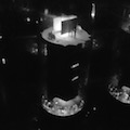
A quick pic from a camera I forgot about. It's near impossible to take photos with when it's not daylight but I'll probably forget to take one when it is so I did one now.
The spaceship light is on when you're running one of the loops and off when in bypass mode. There are green and pink LEDs for the Ignignot and Err sides that are always on so you can switch modes when bypassed.
Shabba.


-
Mike
- I like EL34s
- Posts: 39170
- Joined: Thu Apr 20, 2006 8:30 am
- Location: Edinburgh, Scotland
- Contact:
James wrote:So I finished the loop pedal. Is Awesome. Does exactly what I want and very well. There is a slight click on the bypass switch but it's tolerable..
try soldering 1meg resistors to ground on the input and output lugs of the pedal (or just between the tip and sleeves of the input/output jacks.

"Did you tell him about the jumping?"James wrote:
A quick pic from a camera I forgot about. It's near impossible to take photos with when it's not daylight but I'll probably forget to take one when it is so I did one now.
The spaceship light is on when you're running one of the loops and off when in bypass mode. There are green and pink LEDs for the Ignignot and Err sides that are always on so you can switch modes when bypassed.
Top stuff, dude.


Moar pics. Decals are fucking awesome.
I re-painted my Wooly Mammoth and Fuzz Factory clones to apply decals. I still need to clear-coat these before putting the electronics back in.


Here are two of the mini-boosts. They have matching LEDs but I made the flower on the greenish one a bit too blue. There's a navy blue salt boost to go with these two.


And the looper. You can see the black trimming isn't quite central. I didn't put the spaceship in quite the right place so it's location is a compromise between that and the location of the LED on the spaceship (both are a bit out). I wasn't sure which way around to put the send and return jacks, but with the layout I have planned for my pedal board (looper means I need more cables to be able to do it) the output of the Err chain is nearest the return and the first pedal in the Ignignot chain is to the left of the looper so nearest the send.


I re-painted my Wooly Mammoth and Fuzz Factory clones to apply decals. I still need to clear-coat these before putting the electronics back in.
Here are two of the mini-boosts. They have matching LEDs but I made the flower on the greenish one a bit too blue. There's a navy blue salt boost to go with these two.
And the looper. You can see the black trimming isn't quite central. I didn't put the spaceship in quite the right place so it's location is a compromise between that and the location of the LED on the spaceship (both are a bit out). I wasn't sure which way around to put the send and return jacks, but with the layout I have planned for my pedal board (looper means I need more cables to be able to do it) the output of the Err chain is nearest the return and the first pedal in the Ignignot chain is to the left of the looper so nearest the send.
Shabba.