Got Bored: Made Channel/Reverb Switch
Posted: Sat May 05, 2007 4:56 pm
Got bored and finally got around to making a channel and reverb switch with LEDs for my amp. Laney doesn't actually make a footswitch with LEDs for some reason. The manual gives a nice diagram of how the switching is done which is quite helpful. The one counterproductive thing however is that the drive channel must be on before you can do channel switching, more on this later.
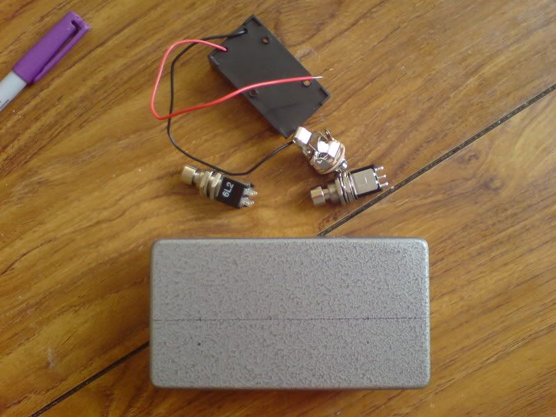
Here are all the basic parts I needed. Two DPDT switches so I can have LED indicator as well, battery compartment and a box. There is a lack of LEDs, because apparently Maplin considers LED bezels web only parts. Anywaybelow is the switching diagram. Notice for the channel switching, when the signal is connect to ground the LED is off. This is because channel 2 is selected by default, so when the signal is disconnected then that channel is on.
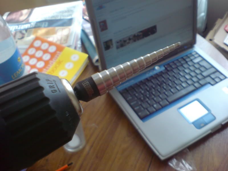
My trusty Unibit. Makes drilling holes in cases effortless.
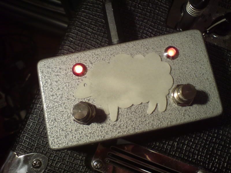
After twenty minutes or drilling and soldering (plus a burnt pinky)
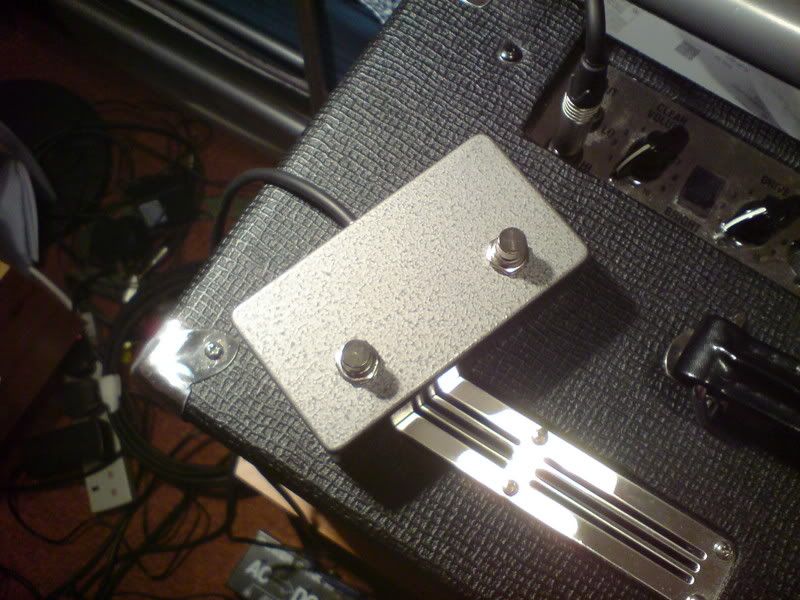
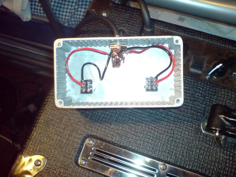
Minus the LED's of course but that is just a quick mod when I actually get the parts. The space between the two switches is exactly enough to put the battery compartment in, its actually tight enough that I wouldn't need to glue it in place. I one thing I did not realise I was lacking was a second stereo jack, so I've soldered the bare cables at the moment.
I'm actually surprised that the channel switching is quiet and pretty instantaneous. Enough that I can't notice it.
Here are all the basic parts I needed. Two DPDT switches so I can have LED indicator as well, battery compartment and a box. There is a lack of LEDs, because apparently Maplin considers LED bezels web only parts. Anywaybelow is the switching diagram. Notice for the channel switching, when the signal is connect to ground the LED is off. This is because channel 2 is selected by default, so when the signal is disconnected then that channel is on.
My trusty Unibit. Makes drilling holes in cases effortless.
After twenty minutes or drilling and soldering (plus a burnt pinky)
Minus the LED's of course but that is just a quick mod when I actually get the parts. The space between the two switches is exactly enough to put the battery compartment in, its actually tight enough that I wouldn't need to glue it in place. I one thing I did not realise I was lacking was a second stereo jack, so I've soldered the bare cables at the moment.
I'm actually surprised that the channel switching is quiet and pretty instantaneous. Enough that I can't notice it.