Simple Wiring Diagram is making my head hurt

Pickups, pedals, amps, cabs, combos

Moderated By: mods

User avatar
Mike
I like EL34s
Posts: 39170
Joined: Thu Apr 20, 2006 8:30 am
Location: Edinburgh, Scotland
Contact:

Simple Wiring Diagram is making my head hurt

Post by Mike »

I was staring at this last night while working from home late into the evening and I don't get it:
http://www.fender.com/support/diagrams/ ... 02APg2.pdf

Now Why the FUCK is the tone it's most trebly when the tone pot is on full (i.e. the Resistance between the wiper and the cap is 1meg)?

This is the circuit that is being made:
Image

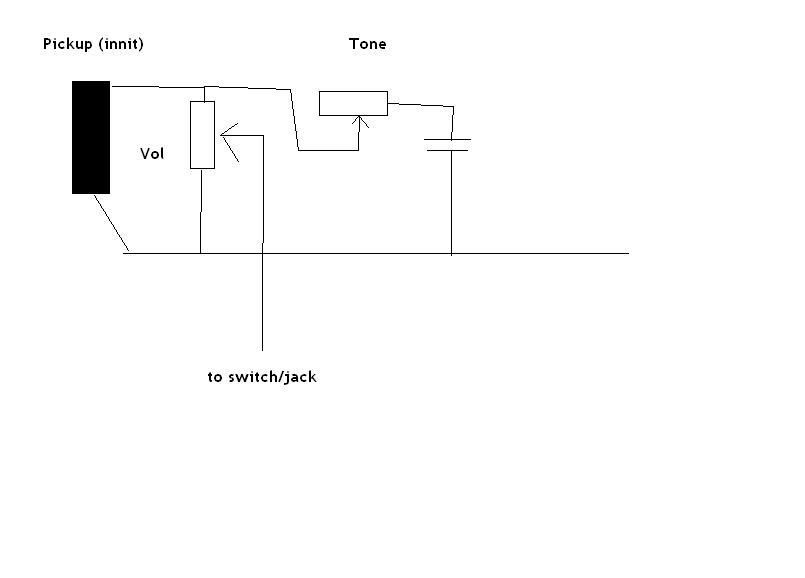
The volume is simple, when set to full (1 meg) you have full output as the signal takes the least resistance path straight to the wiper, which is basically connected to the 'top' lug. Resistance between middle and right lug is 1meg, that's why you don't get much treble loss and maximum outupt.


but that low pass filter really confuses me on the right, I always would do them as signal into a resistor and cap in series to ground, with the output tapped of the mid point, and work out the break freq by 1/(2x pi x RC) and in that case you'd set R to 0 for the maximum treble.

However this isn;t that type of low pass at all, and in fact when R is at it's max like the volume yuo have the most treble. Is tihs as simple as that meaning that it means the signal has to travel through 1 meg to be filtered to ground by the capacitor and therefore full R = least treble loss? Is it this simple or am I missing something complicated? When R is 0 you have a Resistor and a Cap in Parallel with the signal to ground - that's not exactly a classic filter.

I'm a dunce.
User avatar
filtercap
.
.
Posts: 493
Joined: Tue Oct 10, 2006 3:51 am
Location: the information coalmine

Post by filtercap »

Mike wrote:Is tihs as simple as that meaning that it means the signal has to travel through 1 meg to be filtered to ground by the capacitor and therefore full R = least treble loss?
Yes, that's it more or less. The capacitor is a high-pass filter from hot to ground. The R value determines how "available" the filter is to the signal on the hot wire. I think it also determines the corner frequency below which things get filtered. The volume-knob resistance probably has some effect, but I don't know what it is. Apparently it's not a very big effect.
Mo Law-ka
strictly roots
Posts: 3105
Joined: Thu Apr 20, 2006 8:14 pm
Location: a series of tubes

Post by Mo Law-ka »

did you wire it backwards?
i've done that before.
jcyphe wrote: Mo is the most sensible person in this thread.
icey wrote:and thats for the hatters (╯°□°)╯︵ ┻━┻
User avatar
Mike
I like EL34s
Posts: 39170
Joined: Thu Apr 20, 2006 8:30 am
Location: Edinburgh, Scotland
Contact:

Post by Mike »

Mo Rocca wrote:did you wire it backwards?
i've done that before.
No, that's the Fender official wiring.

Thanks Filtercap, it was doing my fucking nut, it all seemed backwards.