Bias Probe Redux Thread for Bubbles
Posted: Fri May 23, 2008 11:37 am
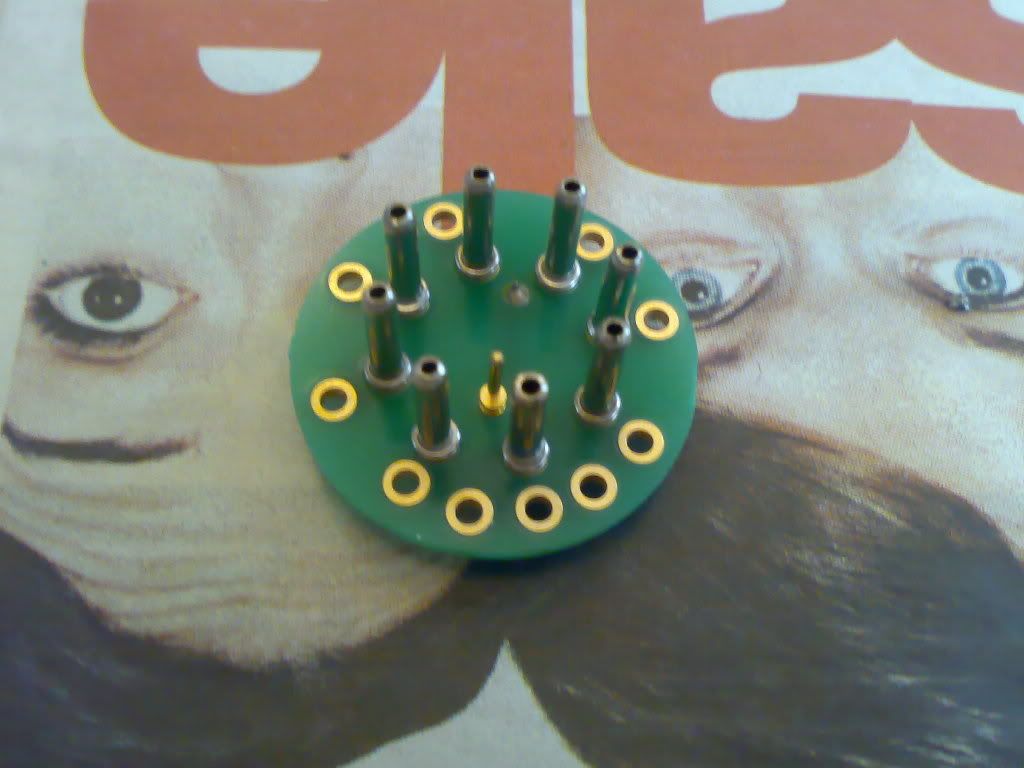
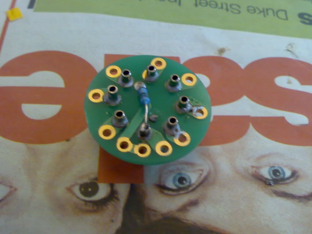
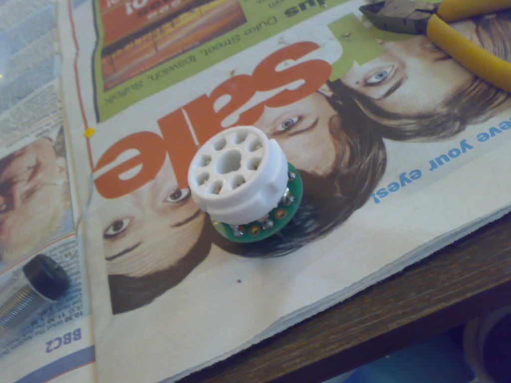
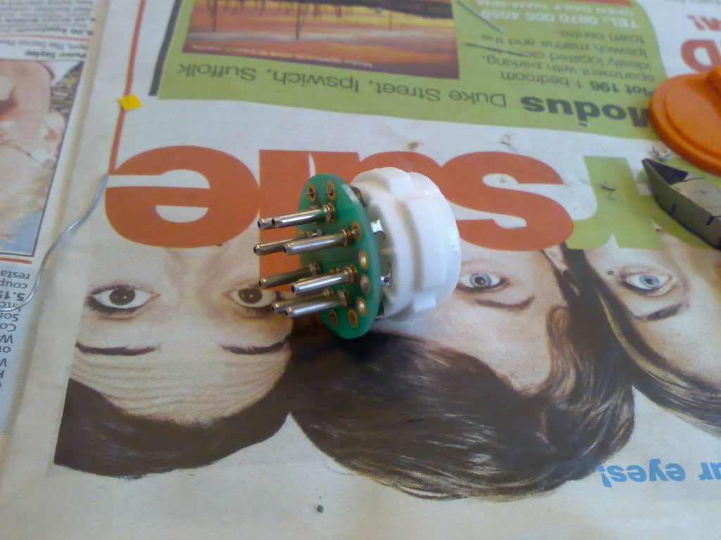
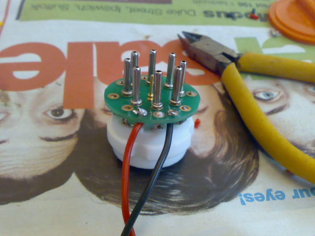
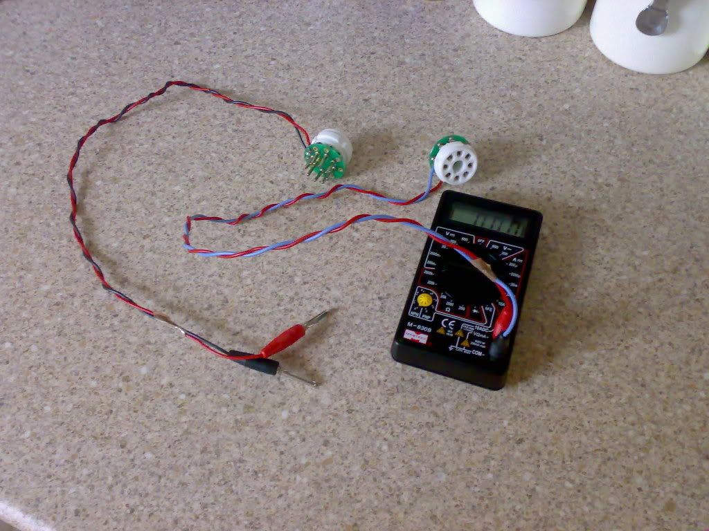
So yeah, basically the 1 ohm resistor is in line with the cathode of the power tube (pin8) and ground (what the pin is connected to on the PCB, by placing it inbetween the ceramic tube socket pin8 and the tube base pin8. This way you can measure the cathode current safely to bias your amp if you don't have bias probe points.
![Image](http://img.photobucket.com/albums/v48/MikeyJazz/Amplifiers/29032008486.jpg)
![Image](http://img.photobucket.com/albums/v48/MikeyJazz/Amplifiers/29032008487.jpg)
![Image](http://img.photobucket.com/albums/v48/MikeyJazz/Amplifiers/29032008488.jpg)
![Image](http://img.photobucket.com/albums/v48/MikeyJazz/Amplifiers/29032008489.jpg)
![Image](http://img.photobucket.com/albums/v48/MikeyJazz/Amplifiers/29032008490.jpg)
![Image](http://img.photobucket.com/albums/v48/MikeyJazz/Amplifiers/29032008491.jpg)