Page 1 of 3
The PRAT pedal, MK2
Posted: Sat Jul 05, 2008 5:03 pm
by Doog
So I rehouse my Ruetz'd RAT a while back with a footswitchable "stock and beyond" pot to bring up the gain. After a while I figured out I didn't really dig it, and rarely needed more gain, so it went back into the old box. (which I Hammerite'D a few weeks ago)..
I had a hunger for an OD pedal, but didn't wanna have another pedal on the board.
So, with a bit of redneck electronics, I piggybacked a 20k pot off the legs of the distortion pot, and stuck a footswitch inline:

Result:


Some herbit crab action going on..
Most pleased. The extra pot current works backwards- clockwise= less gain, but I might keep it for the lulzs. GAINSQUISH I believe I'll label it. Note the red flying leads, I'm gonna put a Jazzmaster slider switch on the back to click the pedal back to stock mode, for mondo gains when needed. THIS PEDAL IS FLEXIBLE.

I also made a DIY Sam and Max shirt. The pic is too small and it's a bit wonky, but it's all good.

I also saw some geniune POWER MANS in the 99p shop yesterday.
This has been a good weekend so far. I'd like to thank Mike and Aen for giving me belief in myself to tinker.
OVER N OUT
Posted: Sat Jul 05, 2008 5:13 pm
by Mike
Nice work dude. Just flip the lugs if you wanna change the way it works, so you're just using it as a gain reduction of the Stock Gain pot? Cool idea. Similar to what we talked about with regard to a "Double Rat"
Posted: Sat Jul 05, 2008 5:17 pm
by Doog
Yeah, I figured I'd have a go since it was a fairly simple idea, just sticking another pot in series. Tried it out with crocodile clips first, all was fine and awesome.
One question: how hard would it be to stick a LED in there for the 2nd mode? I've no idea how they work in regards to being powered and such.
Posted: Sat Jul 05, 2008 5:23 pm
by Tex-czech
powers mans? but I see spiderman too?
Posted: Sat Jul 05, 2008 5:27 pm
by Mike
Doog wrote:Yeah, I figured I'd have a go since it was a fairly simple idea, just sticking another pot in series. Tried it out with crocodile clips first, all was fine and awesome.
One question: how hard would it be to stick a LED in there for the 2nd mode? I've no idea how they work in regards to being powered and such.
Really simple mate.
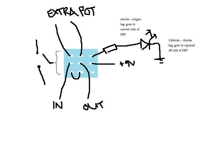
When the 3DPT is orientated with the lugs horizontal (if you know what I mean) then teh switch connects teh middle lugs to the top or bottom lug when you stomp.
Just connect an LED with a 330 ohm current limiting resistor to the same side lug (top or bottom) as your "modded" selection, and the other end of teh LED to ground (pot or casing, whatever). Then connect 9V to the centre lug for that "strip" of the 3PDT. I'll draw a diagram if I've explained this badly.
Posted: Sat Jul 05, 2008 5:34 pm
by Thom
Coolio

Posted: Sat Jul 05, 2008 5:35 pm
by Mike
I did this before i had a proper look at your photo.
As it's orientated in your photo you want to connect +9V to the very centre lug of the 3PDT and the resistor + LED combo to the centre left one. I'll annotate your picture
Posted: Sat Jul 05, 2008 5:38 pm
by Mike
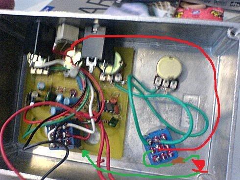
So bascially find +9V from teh DC jack and tap a wire off there, and find GND on teh RAT 3PDT or a jack or whatever (check for continuity with the case) and tap a wire off there. DONE
Posted: Sat Jul 05, 2008 10:34 pm
by Ninja Mike 808
Cool. Bring the noise.
Posted: Sun Jul 06, 2008 11:40 am
by Doog
Awesome, thanks Mikey. And cheers Ninja 'n Lamp
Posted: Sun Jul 06, 2008 12:00 pm
by Hurb
very impressive doog.
Posted: Sun Jul 06, 2008 10:48 pm
by Doog
Lulz, I wouldn't call it impressive, but it's fun and exciting to think how such a simple mod can change a pedal to be twice as useful.
Pulled a red LED from an old OD pedal, so I'm stocked on that front. Mike- when you say a "current limiting resistor", is that a special type, i.e, any old 330 ohm resistor wouldn't work right? And presumably the impedance (330 ohm as you said) would vary the LED's brightness?
Posted: Mon Jul 07, 2008 7:29 am
by Mike
Doog wrote:Lulz, I wouldn't call it impressive, but it's fun and exciting to think how such a simple mod can change a pedal to be twice as useful.
Pulled a red LED from an old OD pedal, so I'm stocked on that front. Mike- when you say a "current limiting resistor", is that a special type, i.e, any old 330 ohm resistor wouldn't work right? And presumably the impedance (330 ohm as you said) would vary the LED's brightness?
Nah it's not a special type of resistor, it's just the job the resistor is doing (limiting the current to the LED from the power source), yeah any old 330 ohm will work (orange orange black black in 4 band code, orange orange brown in 3 band code). And you just up the resistor value to reduce the brightness.
I= V/R = 9V/330 = 27mA.
Here's a website on this sort of shizzle
http://ledcalc.com/
20mA is normally a guide for regular LEDs, 30mA for the superbrights I use. You might wanna go for a 390 ohm to be safe, but a 330 will be fine in my experience.
Posted: Mon Jul 07, 2008 7:34 am
by Mike
Doog wrote:Lulz, I wouldn't call it impressive, but it's fun and exciting to think how such a simple mod can change a pedal to be twice as useful.
Pulled a red LED from an old OD pedal, so I'm stocked on that front. Mike- when you say a "current limiting resistor", is that a special type, i.e, any old 330 ohm resistor wouldn't work right? And presumably the impedance (330 ohm as you said) would vary the LED's brightness?
Nah it's not a special type of resistor, it's just the job the resistor is doing (limiting the current to the LED from the power source), yeah any old 330 ohm will work (orange orange black black in 4 band code, orange orange brown in 3 band code). And you just up the resistor value to reduce the brightness.
I= V/R = 9V/330 = 27mA.
Here's a website on this sort of shizzle
http://ledcalc.com/
20mA is normally a guide for regular LEDs, 30mA for the superbrights I use. You might wanna go for a 390 ohm to be safe, but a 330 will be fine in my experience.
Posted: Mon Jul 07, 2008 11:46 am
by Doog
Cheers fellaaah. Wired that way, will the 2nd "channel" LED still light up if the pedal is off?
Aaaand: the pot only seems to have an effect on half of the dial, much like the stock RAT pots. The pot definately didn't work in that way in the pedal I nicked it from, so is just likely to be down to the RAT design?
Posted: Mon Jul 07, 2008 11:51 am
by Mike
Doog wrote:Cheers fellaaah. Wired that way, will the 2nd "channel" LED still light up if the pedal is off?
Yeah, because it's power isn't dependent on the state of the main RATswitch.
If you want to do only show it's status when the RAT is off then you just tap off the 3DPT power point for the RAT LED.
Posted: Mon Jul 07, 2008 11:55 am
by Doog
Nah, that's exactly what I was after, so I can tell if I'm in Wimpy mode before I launch into a widdle and make a fool of myself.
Posted: Mon Jul 07, 2008 12:22 pm
by Mike
That's what I thought, was just telling you how to do it the other way also.
Posted: Mon Jul 07, 2008 1:51 pm
by Doog
Doog wrote:Aaaand: the pot only seems to have an effect on half of the dial, much like the stock RAT pots. The pot definately didn't work in that way in the pedal I nicked it from, so is just likely to be down to the RAT design?
This probly got missed cause I did a sneaky edit- any ideas? It's not a problem really, just curious.
Posted: Mon Jul 07, 2008 1:56 pm
by Mike
I dunno, my RAT never did that to be honest, it will be doing it because your other pots do I think.
BTW What does it say on the back of your pots in there (any markings like A, B or C?)? and Values?