Page 1 of 2
amp footswitches
Posted: Mon Nov 30, 2009 4:29 pm
by Progrockabuse
as you all know, i use a fender blues deluxe. this comes with a foot switch for changing channels and turning reverb on and off.
i never ever use the channel changing side, as i only use the clean channel.
question is, how easy would be to make a small foot switch just to turn the reverb on and off?
i think i've read somewhere fender wire their foot switches a weird way, so you can only use official ones. plus i'd like a longer cable than the one you get supply with the official foot switch, maybe thicker guitar cable.
ideas? something in the case size of that mini switch of stewart has on is board.
Posted: Mon Nov 30, 2009 4:31 pm
by Mike
Do you has multimeter? We can figure out how it works if so and see if it's possible.
Posted: Mon Nov 30, 2009 4:34 pm
by Progrockabuse
don't think i do. might have to steal my dads. i know if you touch the jack when it's in the amp, you get a shock.
Posted: Mon Nov 30, 2009 4:38 pm
by Mike
WTF Fender.
That sounds properly barmy. What is the connection? Stereo Guitar lead? Does the footswitch have LEDs and no battery?
Posted: Mon Nov 30, 2009 4:41 pm
by Progrockabuse
stereo cable with leds on the switch and no battery.
think i've seen a HRD deluxe foot switch schem, same family of amps.
Posted: Mon Nov 30, 2009 4:42 pm
by stewart
funny, i was recently wondering if there was any way to mod my HRD to make the reverb footswitchable. the footswitch only has channel switching options, which are zero use to me, and the reverb can only be controlled with the knob, again, making it totally useless for my requirements.
Posted: Mon Nov 30, 2009 4:48 pm
by robroe
YOU GUYS NEED A COUGAR1000
REVERB SWITCH ON THE FLOOR MOTHERFUCKAAA
Posted: Mon Nov 30, 2009 4:55 pm
by Progrockabuse


does this help?
Posted: Mon Nov 30, 2009 4:58 pm
by Mike
Sort of. Confirms it is a Stereo TRS connection and that power is coming down somehow. I'm sort of a bit flummoxed as to what is going on there though.
Posted: Mon Nov 30, 2009 6:07 pm
by robroe
ill take mine apart hold on
Posted: Mon Nov 30, 2009 6:18 pm
by chisa
you could build one yourself. simple switch attach it to a stereo jack and see which connections work
Posted: Mon Nov 30, 2009 6:21 pm
by robroe
Posted: Mon Nov 30, 2009 6:24 pm
by chisa
Posted: Mon Nov 30, 2009 6:53 pm
by Pens
chisa wrote:
Can't be right. Ring and Tip can't be connected like that. Wait, maybe it is WTF is that?
The upper connection looks like it carries the 9V or whatever the voltage is for the LED and sends to the ground connection.
Only thing I can think is the switches cause the diodes to create a Voltage drop which is detected at the other end on the amp.
Sorry I can't help otherwise.
Posted: Mon Nov 30, 2009 6:57 pm
by Bill Oakley
Looks like a switching jack to me. Power is coming in through the ring of the cable and when inserted into the jack, it connects the ring to the tip, sending power to the little circuit. Positive voltage reaches the switches through the diodes and LED's which, through the switches, connects back to ground of the jack. When the switches are pressed into the "off" position, it breaks the positive connection.
Posted: Mon Nov 30, 2009 7:56 pm
by Pens
Bill Oakley wrote:Looks like a switching jack to me. Power is coming in through the ring of the cable and when inserted into the jack, it connects the ring to the tip, sending power to the little circuit. Positive voltage reaches the switches through the diodes and LED's which, through the switches, connects back to ground of the jack. When the switches are pressed into the "off" position, it breaks the positive connection.
Yeah this looks like what it is. Good call.
EDIT: The amp side of it probably uses some sort of flip-flop switching like most soft switches on Boss pedals and the like.
Posted: Mon Nov 30, 2009 9:58 pm
by Mike
Chisa's diagram is shite. Ignore it.
It seems odd to me that they'd use diodes to regulate the current, why not resistors. Must be to do with what's on the amp side (relays?)
Posted: Tue Dec 01, 2009 12:52 am
by Bill Oakley
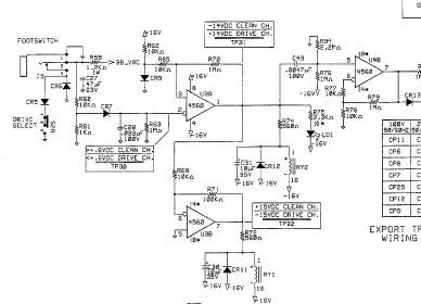
Here's the Blues DLX footswitch section of the schematic:
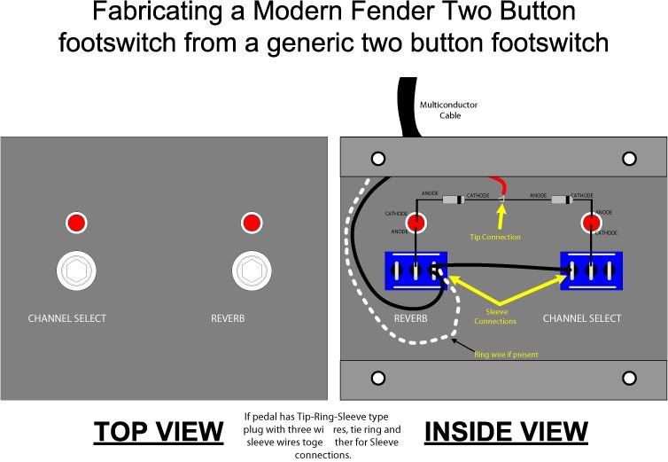
This may help also:
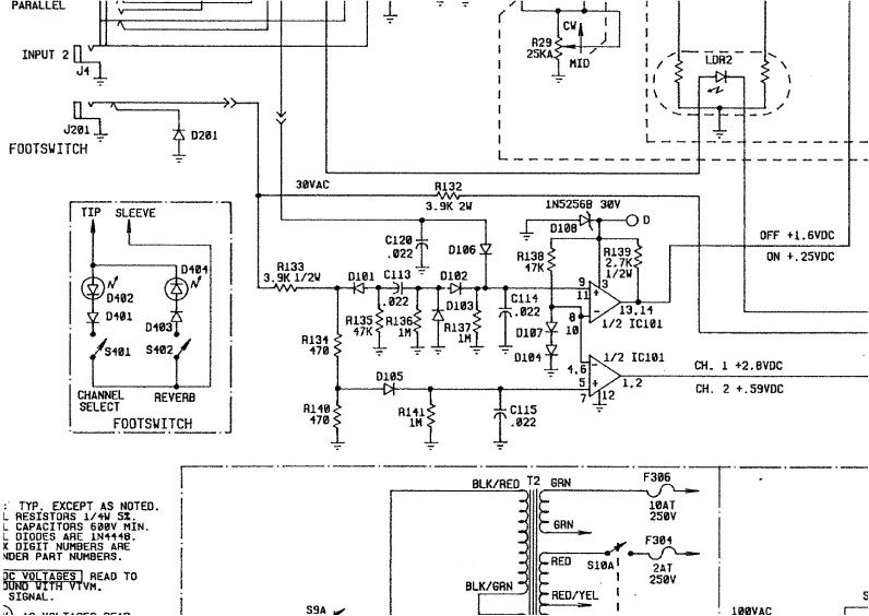
Here is the footswitch schematic for the red knob "Evil" twin:
Posted: Tue Dec 01, 2009 8:30 am
by Mike
Wow. Cheers for all the info. Looks like it doesn't act like a normal "ground the tip or the ring to the sleeve" pedal at all, but that the amp is sensing the LEDs that are on via the tip connection.
I'm not afraid to admit I don't understand it.
Posted: Tue Dec 01, 2009 5:22 pm
by Pens
Mike wrote:Wow. Cheers for all the info. Looks like it doesn't act like a normal "ground the tip or the ring to the sleeve" pedal at all, but that the amp is sensing the LEDs that are on via the tip connection.
I'm not afraid to admit I don't understand it.
I'm not the expert but I believe it works by sensing the voltage drop from the diodes, like how diodes cause different clipping based on their voltage drop. The amp side senses the change of voltage with a flip flop, again if I follow those schems correctly.


