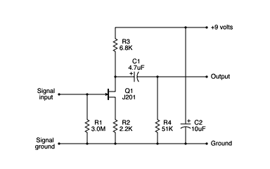
I am doing a simple little preamp project and can't find the proper resistors. Can I substitute, in series, three 1M resistors for a 3.0M resistor?
How about two 2.2k and a 4.7k and a 2.2k to make up for a 51k?
ATTN: electronic geniuses (mike?)
Moderated By: mods
- plopswagon
- cutesy tag
- Posts: 18906
- Joined: Thu Jan 18, 2007 3:32 pm
- Location: 3rd Fret
- Contact:
- timhulio
- Redheaded Stepchild
- Posts: 4693
- Joined: Thu Apr 20, 2006 10:06 am
- Location: London, UK
- Contact:
Poast the schematic. You may be able to substitute rearest values you have. ie, 2.2M for the 3M resistor.
Otherwise, yes three 1M in series= 3M.
Otherwise, yes three 1M in series= 3M.
Last edited by timhulio on Tue Oct 19, 2010 6:19 pm, edited 1 time in total.
- plopswagon
- cutesy tag
- Posts: 18906
- Joined: Thu Jan 18, 2007 3:32 pm
- Location: 3rd Fret
- Contact:
The 3M resistor is just setting the input impedance, and it's probably overkill. Subbing a 1M or 1.5M would work just fine and probably not make any audible difference.
EDIT: also, the 10uf capacitor shouldn't be connected to the signal output, just go between the +9v and ground (it doesn't connect in the schem, but it's hard to read). And there should be a large value capacitor on the signal input to decouple the JFET from the guitar - 1uf or even .22 or .47uf would be plenty.
EDIT: also, the 10uf capacitor shouldn't be connected to the signal output, just go between the +9v and ground (it doesn't connect in the schem, but it's hard to read). And there should be a large value capacitor on the signal input to decouple the JFET from the guitar - 1uf or even .22 or .47uf would be plenty.
- plopswagon
- cutesy tag
- Posts: 18906
- Joined: Thu Jan 18, 2007 3:32 pm
- Location: 3rd Fret
- Contact:
I think the 51K is just there as a pull-down for the negative of the output electrolytic so you don't get a huge thump when you switch it into circuit, sized so that it does not affect the gain too much (assuming mutual conductance results in an effective FET source resistance much lower than 2K2, gain will be 6.8K in parallel with 51K and the input impedance of the next stage, divided by 2K2 - i.e. about 3). TBH you wouldn't notice much difference with just a 47K.
On the input side the gate current is insignificant so the input resistor, whilst referencing the gate to zero for biassing, could be pretty much any value, so can be considered as setting the input impedance. A larger value resistor introduces more Johnson noise, so dropping to 1M is probably good if you're considering it open-circuit and wil reduce the possibility of static damage (less significant than with MOS FETs).
On the input side the gate current is insignificant so the input resistor, whilst referencing the gate to zero for biassing, could be pretty much any value, so can be considered as setting the input impedance. A larger value resistor introduces more Johnson noise, so dropping to 1M is probably good if you're considering it open-circuit and wil reduce the possibility of static damage (less significant than with MOS FETs).


