Page 1 of 2
Troubleshooting a Pedal Build
Posted: Tue Sep 16, 2014 9:35 pm
by Ainm
I bought a big muff kit from musikding. I spent a few hours putting it together, and although I'm happy that I'm getting some kind of sound from it, the switch actually works and so do the volume, tone and sustain controls, although it definitely doesn't sound the way it is supposed to. The output is very low, and there is very little distortion. I don't know very much about electronics, so I don't know how to approach troubleshooting the build. Is there a set of steps that people normally take? Any help would be appreciated.
Posted: Wed Sep 17, 2014 8:53 am
by Fakir Mustache
The most obvious is go back and check all the colour codes to make sure you didn't solder the wrong resistors in.
You could have fried the caps or transistors if you didn't use a heat sink too.
Posted: Wed Sep 17, 2014 11:56 am
by timhulio
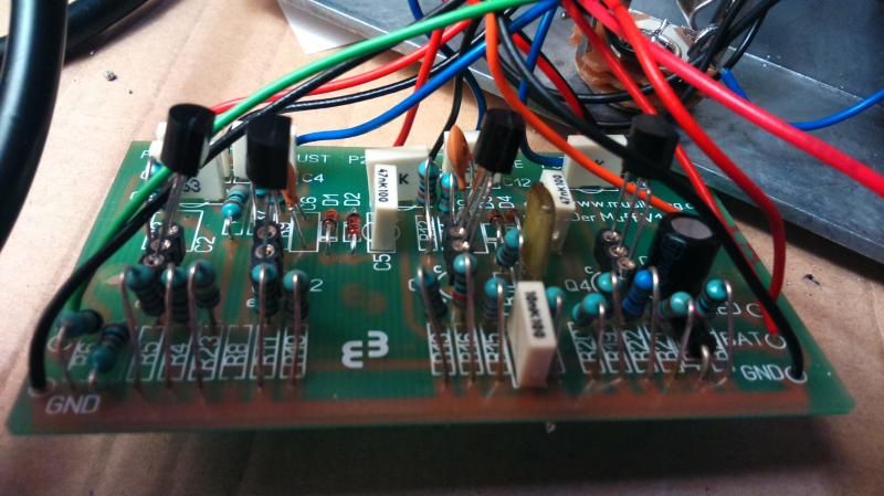
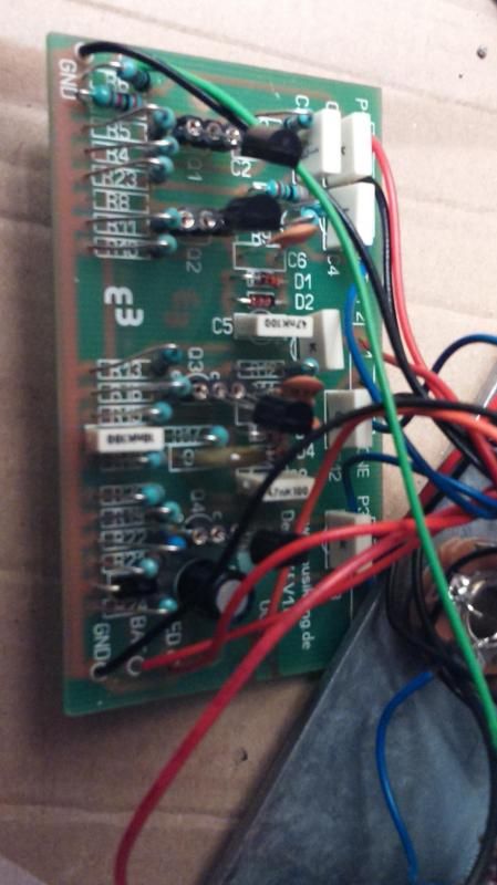
Show us a pic.
Posted: Fri Sep 19, 2014 9:49 am
by Ainm
Posted: Fri Sep 19, 2014 9:53 am
by Ainm
Fakir Mustache wrote:The most obvious is go back and check all the colour codes to make sure you didn't solder the wrong resistors in.
You could have fried the caps or transistors if you didn't use a heat sink too.
I didn't use a heat sink, but I used sockets for the transistors, so they should be fine, at least. I really hope I don't have to go back over every single resistor; I think that would be a last resort for me.
Posted: Fri Sep 19, 2014 12:59 pm
by NickS
I hate to be negative but..
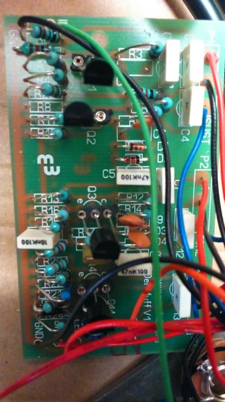
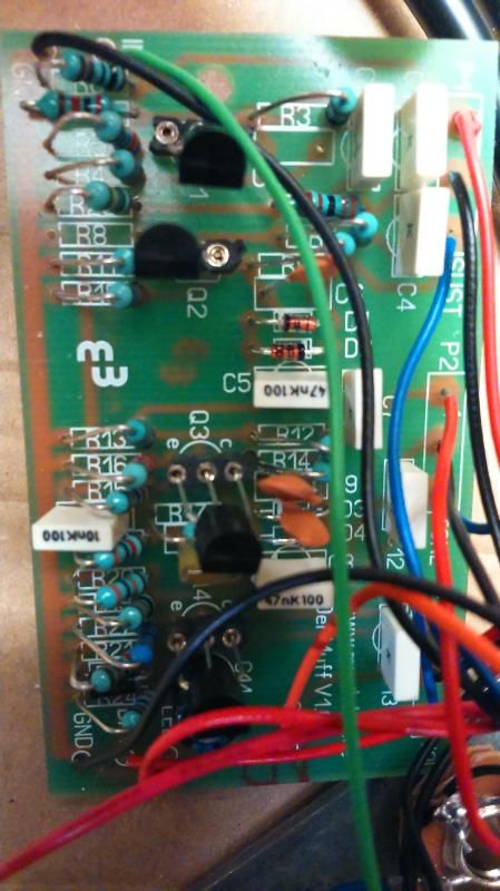
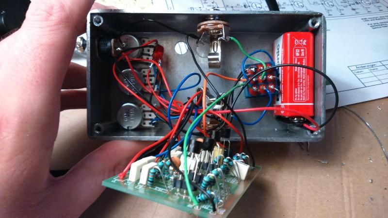
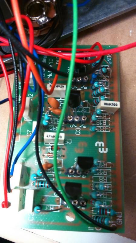
With those pics, mostly taken from overhead, and that lighting we can't read the coloured bands on the resistors. The wiring is also a bit of a rat's nest so that on the one reasonable picture of the wiring to the pots I can't work out what's going where.
Posted: Fri Sep 19, 2014 1:03 pm
by NickS
Pro tip from our cable installer guys: where you've got cables/wires the same colour, use a permanent marker (Sharpie) to put stripes (1 on the first, 2 on the second, 3 etc) on each end of each wire. Then when you take pictures of each pot,switch/jack socket/circuit board you should be able to match them up even with a rat's nest.
Posted: Fri Sep 19, 2014 1:32 pm
by Mike
>>The output is very low, and there is very little distortion
most likely a resistor value cock up
double check them all in order using the colour chart against the values in the build guide.
Posted: Fri Sep 19, 2014 1:33 pm
by Mike
WHERE THE FUCK IS R8?
Posted: Fri Sep 19, 2014 8:40 pm
by NickS
Mike wrote:WHERE THE FUCK IS R8?

Posted: Fri Sep 19, 2014 8:48 pm
by theshadowofseattle
Mike wrote:WHERE THE FUCK IS R8?
where's r8, m8?
Posted: Sat Sep 20, 2014 8:46 am
by Mike
In next week's episode we answer the question:
Where the fuck is C2?
Posted: Sat Sep 20, 2014 9:12 am
by Fakir Mustache
Ainm wrote:Fakir Mustache wrote:The most obvious is go back and check all the colour codes to make sure you didn't solder the wrong resistors in.
You could have fried the caps or transistors if you didn't use a heat sink too.
I didn't use a heat sink, but I used sockets for the transistors, so they should be fine, at least. I really hope I don't have to go back over every single resistor; I think that would be a last resort for me.
Naw, resistors don't fry so easily, that's why they're called resistors. <boom, tchak>
The caps could possibly fry, but more importantly check if the spaghetti is connected properly and maybe also need to put in the missing components.
And maybe also a pic of the soldering on the back if that doesn't fix it. Not only could you have a bad connection, but also an unintended bridge.
Posted: Sat Sep 20, 2014 11:47 am
by Concretebadger
Posted: Sat Sep 20, 2014 1:45 pm
by Ainm
Mike wrote:WHERE THE FUCK IS R8?
Based on the documentation on the musikding website there is no R8 or C2. The link below has a pic from the website. I'm very new to electronics, I thought I was supposed to just leave those out. Was I supposed to jumper them or something?
http://diy.musikding.de/wp-content/uplo ... ffwire.pdf
Posted: Sat Sep 20, 2014 2:03 pm
by Ainm
NickS wrote:Pro tip from our cable installer guys: where you've got cables/wires the same colour, use a permanent marker (Sharpie) to put stripes (1 on the first, 2 on the second, 3 etc) on each end of each wire. Then when you take pictures of each pot,switch/jack socket/circuit board you should be able to match them up even with a rat's nest.
Thanks for the tip. I'll bear it in mind if I try this again.
Posted: Sun Sep 21, 2014 10:31 pm
by NickS
Mike wrote:In next week's episode we answer the question:
Where the fuck is C2?
C2 is an option, you can put something in there to simulate the junction capacitance of a Germanium transistor if you're using silicon, to slug the high frequency gain a bit.
Posted: Sun Sep 21, 2014 10:40 pm
by NickS
Ainm wrote:Mike wrote:WHERE THE FUCK IS R8?
Was I supposed to jumper them or something?
No, but the curious thing is that there is an R8 in at least one schematic/parts list.
http://diy.musikding.de/wp-content/uplo ... nbomen.pdf
http://diy.musikding.de/wp-content/uplo ... nbomen.pdf
Which Big Muff kit did you buy?
Posted: Mon Sep 22, 2014 12:37 am
by Mike
Ainm wrote:Mike wrote:WHERE THE FUCK IS R8?
Based on the documentation on the musikding website there is no R8 or C2. The link below has a pic from the website. I'm very new to electronics, I thought I was supposed to just leave those out. Was I supposed to jumper them or something?
http://diy.musikding.de/wp-content/uplo ... ffwire.pdf
Nah it seems like you did the correct thing
Did you double check all the values yet?
Posted: Sun Sep 28, 2014 9:36 pm
by Ainm