Page 1 of 1
bass/guitar bazz fuzz
Posted: Thu Oct 01, 2015 8:25 pm
by vojtasTS29

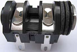
Guys, i am trying to build a pedal in a soapbox here, and i am failing terribly to wire the jacks. Can someone draw it over my pic for me? Thanks

Posted: Thu Oct 01, 2015 8:44 pm
by timhulio
No probs. What sort of jack are you using?
Posted: Thu Oct 01, 2015 8:50 pm
by vojtasTS29
I want to have mono on both sides. I am not really a stereo guy. I am just making a pedal for my bass player, because i kinda changed in songwriting and she needs fuzz. And then she told her friends, so i have to build two or three of those. I am trying to experiment with the diode switching, where the led should make the sustain better with guitar, where this just seems to cut off a lot... and the standard silicon diode for bass.
Posted: Thu Oct 01, 2015 9:23 pm
by timhulio
Great boss. You need a stereo jack on the input so you can unplug it and prevent the battery draining (if you're using battery power ... are you?)
What sort of jacks are you using?
These ones:

Or these:

Or these:
Posted: Thu Oct 01, 2015 9:25 pm
by vojtasTS29
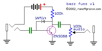
I mean, if someone can just redraw the bazz fuss scheme with switchable 1N914/LED, the same caps and on off switch and showed me which wires will i solder to what things on the jacks(this is where i have the biggest problem) and maybe give me some advice on the cap value and transistors. That would be super great
Posted: Thu Oct 01, 2015 9:32 pm
by timhulio
Yes, that's what I intend to do. Just tell me what sort of jacks you have.
Posted: Thu Oct 01, 2015 9:40 pm
by vojtasTS29
Oh sorry. I didnt see your reply. It wasnt there when i wrote the last message. Yes, i am using the first kind of jacks.
Oh and yes. Baterry powered
Posted: Thu Oct 01, 2015 9:52 pm
by timhulio
Here's what the jack terminals in the schematic refer to.

Of course you'll want to wire in a footswitch so you can actually bypass the thing. So check the Beavis Audio diagram for that.

Posted: Thu Oct 01, 2015 10:01 pm
by vojtasTS29
Thank you very much
. There is only one brutal fail. They dont sell those foot switches in this country. Noone does. Not even the biggest electronics shipper GME. So i am going to have to make a makeshift solution somehow.
Posted: Thu Oct 01, 2015 10:11 pm
by timhulio
Get them from abroad via eBay or Tayda or even Smallbear. Or Banzai if you must.
Posted: Thu Oct 01, 2015 10:13 pm
by vojtasTS29
Probably wont use a led indicator. You can get two row switches(with 6 pins) easily
Posted: Thu Oct 01, 2015 10:21 pm
by NickS
Posted: Fri Oct 02, 2015 9:46 am
by vojtasTS29
Thank you very much guys
. So this should be right, right? I wonder if anybody has any advice about the cap value. And also if the 2n2089 will increase the sustain to make it less robotic. Also a trim pot added to bias it.

Posted: Fri Oct 02, 2015 11:08 am
by timhulio
The cap values sound about right. Lower them if it sounds too wooly and indistinct. The input cap will have to be a polarised electrolytic cap. Why not just use .22uf for the input cap too? 1N914 is a silcon diode. I'm not sure what you're trying to achieve with the diode switch here, as these aren't clipping in this application. 2N5089 will sound the same as 2N5088 in this circuit. Best build the thing on breadboard without all the bypass switch stuff while you experiment with different components. Otherwise you'll just be soldering and desoldering stuff until you burn em!
Posted: Fri Oct 02, 2015 1:54 pm
by vojtasTS29
Well, this guy
home wrecker says that the voltage of the diode has brutal impact on the sound. Those cap values were taken i think straight from some guy who did tests with different ones
Posted: Fri Oct 02, 2015 2:35 pm
by vojtasTS29
i am also considering a 2N2222A transistor
We'll see how that turns out. i liked the sound on a video where guy did comparsions of the sound with many components, so i asked him about cap and resistor values, too.
Posted: Fri Oct 02, 2015 8:33 pm
by NickS
Using that trimpot without a series resistor to limit the current may be a recipe for burning out the transistor and part of the trimpot. Maximum continuous collector current is 50mA for the 2N5088/5089 so I'd stick a 180 or 220 ohm resistor in between the transistor and the trimmer.
There's no emitter resistor which has a couple of impacts.
1. The collector voltage can't vary an awful lot given that the base of the transistor isn't going to go much above .7V, so the collector can only swing between around 0.2V and whatever the drop is across the diode(s) between collector and base. In this case the maximum voltage swing is going to be affected by the choice of diodes. Effectively they will be clipping.
2. The input impedance is going to be the input impedance of the transistor i.e. gain x emitter resistance, in parallel with the impedance of the diodes divided by the stage gain. What goes in front of this box will probably make quite a difference to the overall sound. If driving it straight from the guitar you might want to try putting an input load resistor in series with the input (between the cap and the transistor base) and see how that affects things.
Say the total diode drop to bias the transistor on is 2 V, the emitter current at steady state is largely going to be determined by the value of the collector load trimpot and the battery voltage; (9 - 2) V/Rtrim. If we say 7 V/100K ohms, that's 70 uA. With the mutual conductance of silicon at 40 mA/V per mA, mutual conductance will be 2.8 mA/V and the emitter impedance will be around 360 ohms. The input impedance of the transistor would be that times the stage gain (100360/360 = about 280) i.e. 100360 ohms as long as the transistor's small-signal gain is comfortably more. Probably the input impedance is going to be most affected by the dynamic impedance of the diodes divided by the effective stage gain.
If the trim pot (and limiting resistor) goes down to 1 K, emitter current is around 7 mA, emitter impedance is 3.6 ohms and the input impedance has dropped down to just over 1 K (stage gain is still 280). This is going to have quite an impact when it comes to the value of the input capacitor and the desired lower cut-off frequency.
