Page 1 of 1
Blown resistors on Traynor TS-50b pcb
Posted: Sun Dec 04, 2016 3:55 am
by cobascis
Hello all, long time no see.
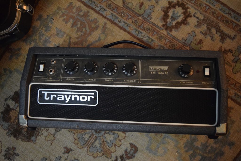
I just scored a Traynor TS50b (aka Shellac bass tone) for $25, knowing that it would turn on but not make sound.
Upon opening it, I found this:
The TS50B:
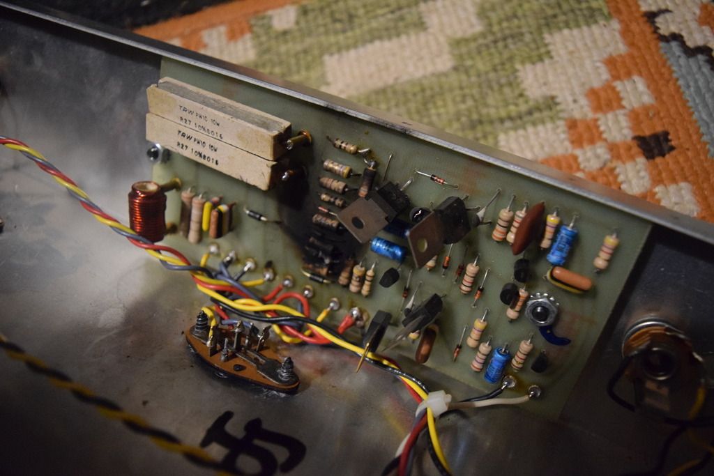
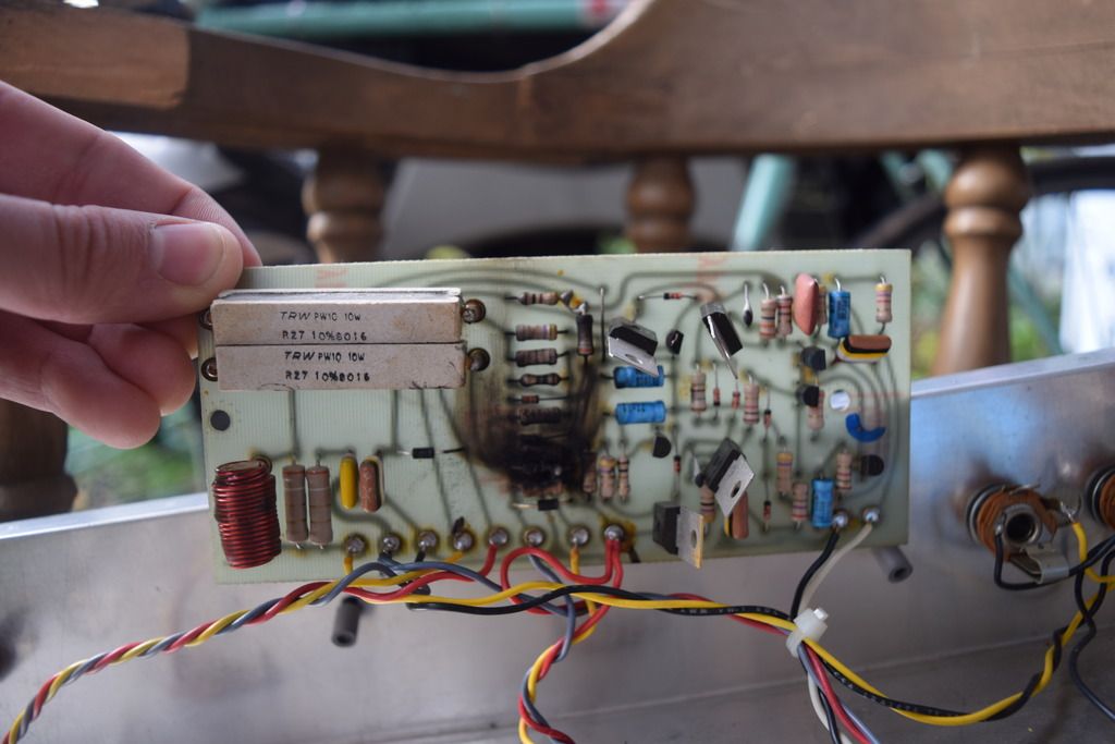
Here is the damage:
Maybe someone ran it with the wrong impedance cab? I've never dealt with something like this. Should I be worried that the transformer is fucked?
It looks like the back of the pcb is OK, so I'm hoping I can just replace these components and call it a day.
I found a schematic online, but am having trouble identifying the values of the resistors I need to replace. Could anyone make a list of those in the burnt out area?
Any pointers on to whether replacing just these resistors or if this might be a deeper problem would be appreciated!
Thanks!
Posted: Sun Dec 04, 2016 3:56 am
by cobascis
Schematic:

Posted: Sun Dec 04, 2016 9:06 pm
by cobascis
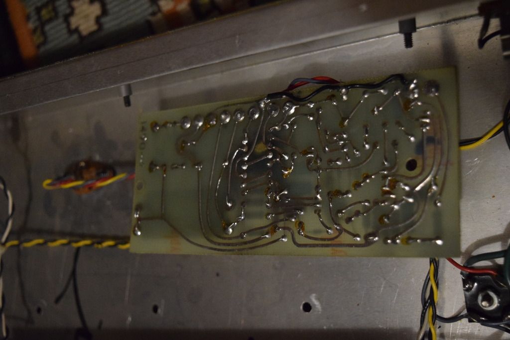
Here is a shot where you can see the traces. Can anyone help name those components I should replace by referencing the schematic?
Posted: Sun Dec 04, 2016 9:15 pm
by Doog
*Beams NickS batsignal into the sky*
Posted: Mon Dec 05, 2016 4:17 am
by sunshiner
I am too ignorant/lazy to make myself read schemes. I had minor experience with fixing some electrical devices and frequently blown off resistors were not the reason of the damage, but a consequence. If nobody helps you here, try to post the scheme on a website of amp building enthusiasts
Posted: Mon Dec 05, 2016 2:16 pm
by NickS
At work right now, will look when I can.
Posted: Mon Dec 05, 2016 3:12 pm
by NickS
Well, there's more than the burnt resistor.

- traynor_blown.png (237.99 KiB) Viewed 375 times
Blown-apart transistor... there's some burning on the PCB that should be drilled/Dremelled out and repaired with resin... You probably need to sniff around some of the other transistors with a meter to see if anything else is gone. First step is to clean it up with alcohol and a stiff brush, make sure there's no loose carbon around. Take out the broken resistor so you can clean up the burned area and see how much you need to cut out; the little diode and other resistors will probably clean up OK. I'll try to match the other components with the schematic.
Posted: Tue Dec 06, 2016 11:09 pm
by NickS
This is going to be fun. Most of those transistors are no longer available so you'll need substitutes...
Posted: Wed Dec 07, 2016 11:19 am
by Fakir Mustache
NickS wrote:This is going to be fun. Most of those transistors are no longer available so you'll need substitutes...
Depending on how many months or years it's going to take for him to learn to read a schematic and operate a multi-meter. Definitely years if he's going to have to calculate if each component is good, I'm not even able to do that.
I know there are programs available, you can draw the schematic and it'll calculate the voltages and other readings at all the points in the circuit. I have a free one, but haven't figured out how to draw the circuit or do anything else.
Posted: Wed Dec 07, 2016 4:50 pm
by NickS
Be fair, you don't have to know how to read a schematic. When I was in repair at Ferranti we'd get the part from store and tell the wire mech what component to replace. Using a multimeter isn't rocket science and a blown transistor is usually short or open circuit - if you can isolate it from the surrounding components or make allowance for them.
I was wondering whether it would be easier simply to replace the board with an integrated amp module but (a) they all seem to be designed for 4 ohms so the voltage rails are wrong and (b) they all seem to be stereo. I'm trying to do an overlay that'll be useful to other owners while I'm working out the component placement.
Posted: Thu Dec 08, 2016 12:25 pm
by sunshiner
Yes, it is not that hard to check and replace a transistor. You need some source to open it and check if it opens and closes. There is all information on the web about substitute transistors. Also reading schemes is not that hard, it takes some dedication, but if you have the discreption of the scheme, you'll be able to understand how it works. Especially if you start with simple schemes. I never really dived deep in the topic... because you've got to love it and I obviously don't
Posted: Thu Dec 08, 2016 1:02 pm
by NickS
Damn, assigned the same designation to two resistors... now I have to start renumbering R12 to R24. Plus there are two 100nF caps that aren't in the schematic, one decoupling the -35V but the other... PCB pictures aren't clear enough to be sure.
Posted: Fri Dec 09, 2016 4:11 pm
by sunshiner
^ you got it from the photos?
Posted: Fri Dec 09, 2016 5:11 pm
by NickS

- 790713_TS50B_amp_board - Copy.png (93.31 KiB) Viewed 374 times

- TS50B_power_amp_overlay_small.png (1.42 MiB) Viewed 374 times
Posted: Sat Dec 10, 2016 8:34 am
by sunshiner
You remind me some old qualified engineers I worked with NickS, you too have that crazy skillz
Posted: Sun Dec 11, 2016 12:17 am
by NickS
I'll take that as a compliment...

I could have done with sharper pictures more square-on but I think that's pretty accurate. The worrying thing is that the blown transistor and the burnt resistor are in different areas of the schematic, so possibly widespread damage and possibly at least one blown output transistor as well. I gather the TS-50B preamp has a good reputation so it may be worthwhile repairing, or just buying a LM3875 based kit to replace the power section using the existing 35v supplies.
Posted: Wed Dec 14, 2016 12:54 pm
by NickS
From
Talkbass.comRoland GR 88 wrote:You can always call Yorkville in Pickering Ont. and ask to speak to their tech dept. They're very helpful and always willing to chat.
May be an option? You could ask them if they have some recommended replacements for the obsolete transistors... I don't know what your soldering skills are like.